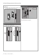
L9000-Series electrified installation instructions
Schlage • L-Series service manual • 229
© Allegion 2015
P516-871 Rev. 10/15-d
Customer Service
1-877-671-7011
www.allegion.com/us
Deadbolt Monitor (DM)
Deadbolt Monitor (DM) identifies the status of the deadbolt (extended or retracted). Normally open, normally closed, and common connections are
provided. Note: Deadbolt monitor is only available on deadbolt models. Electrical rating: 3 A, 125 V AC; 2 A, 30 V DC.
Latchbolt Monitor (LX)
Latchbolt Monitor (LX) identifies the status of the latchbolt (extended or retracted). Normally open, normally closed, and common connections
are provided. Electrical rating: 3 A, 125 V AC; 2 A, 30 V DC.
Door Position Sensor (DPS)
Door Position Sensor (DPS) detects the position of the door, open
or closed, by utilizing a sensor in the mortise lock to detect a magnet
located in the door strike. Normally open, normally closed, and common
connections are provided. Note: DPS is not available on deadbolt models.
Max voltage 175 VDC, max current 0.250 A
DPS strike box
Strike
(10-072 shown)
Magnet
Allegion Connect
The L909X-Series and LM929X-Series electrified mortise locks are furnished with Allegion Connect, a factory-installed Molex® connector system that
provides simplified installation and maintenance. The system utilizes quick-connect harnesses and hinges. As an alternative installation method, the
Molex connector may be cut off and the lock installed with traditional wire splicing methods.
Note: The items listed and shown below reflect options that may or may not be included with your specific model.
Variable length wiring
harness (6" to 192")
EPT or electrified hinge
6” wiring harness
To
power
supply
RX/LX/DPS
RX/LX/DM
1 2
3 4
5 6
7 8
1 2
3 4
4-pin
connector
1 2
3 4
5 6
7 8
1 2
3 4
8-pin
connector
L909X available options:
RX = Request to exit
DM = Deadbolt monitor
DPS = Door position sensor
LX = Latchbolt monitor
LM929X available options:
None
See charts below for wire colors.
8-Pin
Lock
Connector
Harness
Connector
Purpose
Function
Wire
Color Pin
Pin
Wire
Color
EL / EU
Power*
Black
1
▬►
1
Red
Power*
Black
2
▬►
2
Black
RX
Normally Open (NO)
Blue
3
▬►
3
Blue
Normally Closed (NC)
Yellow
4
▬►
4
Yellow
Common (C)
Green
5
▬►
5
Green
LX
Normally Open (NO)
Gray
6
▬►
6
Gray
Normally Closed (NC)
Violet
7
▬►
7
Violet
Common (C)
White
8
▬►
8
White
* Lock auto-detects GND, +12 or +24 V DC
4-Pin
Lock
Connector
Harness
Connector
Purpose
Function
Wire
Color
Pin
Pin
Wire
Color
DM
Normally Open (NO)
Orange
1
▬►
1
Orange
Normally Closed (NC)
Brown
2
▬►
2
Brown
Common (C)
Pink
3
▬►
3
Pink
not used
4
4
Tan
DPS
Normally Open (NO)
Green/black
1
▬►
1
Orange
Normally Closed (NC)
Red
2
▬►
2
Brown
Common (C)
White/black
3
▬►
3
Pink
not used
4
4
Tan
Summary of Contents for Schlage D Series
Page 1: ...Schlage Manuals 2016...
Page 2: ...D Series Service manual...
Page 3: ......
Page 4: ......
Page 5: ......
Page 6: ......
Page 7: ......
Page 8: ......
Page 9: ......
Page 10: ......
Page 11: ......
Page 12: ......
Page 13: ......
Page 14: ......
Page 15: ......
Page 16: ......
Page 17: ......
Page 18: ......
Page 19: ......
Page 20: ......
Page 21: ......
Page 22: ......
Page 23: ......
Page 24: ......
Page 25: ......
Page 26: ......
Page 27: ......
Page 28: ......
Page 29: ......
Page 30: ......
Page 31: ......
Page 32: ......
Page 33: ......
Page 34: ......
Page 35: ......
Page 36: ......
Page 37: ......
Page 38: ......
Page 39: ......
Page 40: ......
Page 41: ......
Page 42: ......
Page 43: ......
Page 45: ...Schlage small format cores Service manual...
Page 46: ......
Page 48: ......
Page 49: ...Schlage SFIC service manual 5...
Page 58: ......
Page 59: ......
Page 62: ......
Page 64: ......
Page 107: ......
Page 109: ...Everest full size cylinder Service manual...
Page 110: ......
Page 129: ...B Series Service manual...
Page 130: ......
Page 150: ...22 Schlage B Series service manual Locks...
Page 165: ...Options and Parts Schlage B Series service manual 37 Notes...
Page 166: ...38 Schlage B Series service manual Options and Parts Notes...
Page 167: ......
Page 169: ...ND Series Service manual...
Page 270: ...L Series Service manual...
Page 271: ......
Page 293: ...24 Schlage L Series service manual...
Page 359: ...90 Schlage L Series service manual...
Page 444: ...Schlage L Series service manual 175...
Page 499: ...230 Schlage L Series service manual...
Page 500: ......
Page 502: ...AL Series Service manual...
Page 503: ......
Page 505: ......
Page 542: ...A Series Service manual...
Page 543: ......
Page 545: ......
Page 572: ......


