background image

226  •  Schlage  •  L-Series service manual

L400-Series 180 degree indicator installation instructions

5

THUMB TURN:

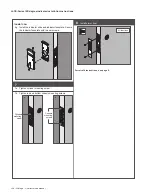
6g  Install the indicator slide and indicator faceplate. Secure 

the indicator faceplate with two set screws.

7a  Tighten cylinder mounting screw.

7b  Tighten top and bottom chassis mounting screws.

Cylinder 

mounting 

screw

a

b

Chassis 

mounting 

screws

Install armor front

All functions

For retrofit instructions, see 

page 6.

Summary of Contents for Schlage D Series

Page 1: ...Schlage Manuals 2016...

Page 2: ...D Series Service manual...

Page 3: ......

Page 4: ......

Page 5: ......

Page 6: ......

Page 7: ......

Page 8: ......

Page 9: ......

Page 10: ......

Page 11: ......

Page 12: ......

Page 13: ......

Page 14: ......

Page 15: ......

Page 16: ......

Page 17: ......

Page 18: ......

Page 19: ......

Page 20: ......

Page 21: ......

Page 22: ......

Page 23: ......

Page 24: ......

Page 25: ......

Page 26: ......

Page 27: ......

Page 28: ......

Page 29: ......

Page 30: ......

Page 31: ......

Page 32: ......

Page 33: ......

Page 34: ......

Page 35: ......

Page 36: ......

Page 37: ......

Page 38: ......

Page 39: ......

Page 40: ......

Page 41: ......

Page 42: ......

Page 43: ......

Page 44: ...homes and businesses Allegion employs more than 7 800 people and sells products in more than 120 countries across the world Allegion comprises 23 global brands including strategic brands CISA Inter ex...

Page 45: ...Schlage small format cores Service manual...

Page 46: ......

Page 47: ...m Cylinders 7 If You Are Familiar With Pinning Best Style Cores 7 Schlage SFIC Keys 8 If You Are Not Familiar With Pinning Best Style Cores 10 6 Pin Combinating Example Tip to Bow 11 Troubleshooting 1...

Page 48: ......

Page 49: ...Schlage SFIC service manual 5...

Page 50: ...the end user Shipping the order prevents locksmiths and distributors from having access to keys and cores without the permission of the end user B234 and B235 restricted keyways are for locksmiths an...

Page 51: ...ot use Kaba Peaks bottom pins as they are 003 too short for Schlage cores 3 For security reasons Schlage advises against using colored bottom pins The colors can be read through the keyway with a lock...

Page 52: ...leaving a clear passage down the pin chambers to the plug surface Check for uniform space here Turn plug about 90 Control lug extended 4 There are two shear lines in each chamber one for the operating...

Page 53: ...mpress properly 9 Cap the core a Slide the core into the capping block b Install a spring into each chamber c Slide cap on at the top of each chamber Pins fall into keyway Plug turned too far d Chambe...

Page 54: ...cut is 1 bottom pin Deepest minus shallowest is 2 master pin Formula of C 10 P BU 9 10 3 16 We now have 1 2 16 19 units of stuff loaded 4 top pin must be added to total 23 Chamber 4 Shallowest operat...

Page 55: ...ncluding the capping process leaving the remaining chambers empty This allows you to test all keys chamber by chamber until you build up enough accuracy and confidence to handle all chambers at once I...

Page 56: ...e is designed to replace cores by Best Arrow and others Schlage s key cuts are read and written Tip to Bow This is the opposite of other Schlage keys but standard for small format IC 35 400 Facility c...

Page 57: ...A2 System Pin Kit 40 071 A2 System Key Gage 40 128 9 8 7 6 5 4 3 2 1 0 Capping Block 40 137 Capping Pin 40 138 Ejector Pin 40 136 Pin Kit Refills 100 pack Bottom Pins 0A 34 800 1A 34 801 2A 34 802 3A...

Page 58: ......

Page 59: ......

Page 60: ...omes and businesses Allegion employs more than 7 800 people and sells products in more than 120 countries across the world Allegion comprises 23 global brands including strategic brands CISA Interflex...

Page 61: ...Primus Primus Primus XP EverestTM Primus Everest Primus XP Everest 29TM Primus Everest 29 Primus XP Service manual...

Page 62: ......

Page 63: ...imus control register MS E160 22 Issuing ID cards 22 Managing lost stolen or invalidated cards 22 Managing key blank inventory 23 Key control procedures end user controlled systems 23 Signature verifi...

Page 64: ......

Page 65: ...st 29 keys Everest 29 Everest and Classic key systems can be enhanced and restricted to limited distribution with the addition of Primus XP Primus XP Schlage s high security sidebar cylinder mechanism...

Page 66: ...only one side Same as Classic Keys shape with limited stamping space The word Primus is stamped on the front of the key bow Standard key is embossed on one side Plain bow available 20 larger than Cla...

Page 67: ...icted keyways Special non stock keyways set aside for limited use and a higher degree of key control A letter of authorization from the end user is required to process orders for Restriced keys blanks...

Page 68: ...accommodate the finger pins When the key is inserted each of the side bit cuts lifts the finger pin and rotates it so that the notches in the side bar align with the notches in the back of the finger...

Page 69: ...KS KC and Rim standard and lockout All competitive locks that accept Everest Primus will also accept the modular cylinders Key in knob to modular mortise or rim cylinder conversion Modular housing int...

Page 70: ...echanism but the cap pin also serves to drive the cam or tailpiece Housings and tailpieces manufactured before the Primus core was introduced only had clearance for the conventional cap pin Now all FS...

Page 71: ...t be at least a 3 depth and the sixth cut must be equal to or deeper than the fifth cut 2 Lockout cylinders must NOT be master keyed When keys are inserted quickly master pins may remain in the shell...

Page 72: ...de bitting already milled Pins and springs Bottom pins Size Length Part no 0 165 34 300 1 180 34 301 2 195 34 302 3 210 34 303 4 225 34 304 5 240 34 305 6 255 34 306 7 270 34 307 8 285 34 308 9 300 34...

Page 73: ...s raise and swivel the finger pin in order to align the notch in the pin to the notch in the side bar If a side cut is misread the pin will not align with the side bar by being too high too low or rot...

Page 74: ...igit zip code exclusivity of side bit milling Small businesses Restaurants Doctor s offices Dealer exclusive Owned stocked by dealers resold to end users Keys bear unique Dealer ID based upon three di...

Page 75: ...ble side bittings of the lower level keys Level 1 cylinders are shipped 0 bitted All keying is done in the field Sequence numbers The sequence number is a 4 digit code which identifies the combination...

Page 76: ...date a signature before duplicating any Level 1 keys to maintain accurate records of all keys cut Keyways and keying options Level 1 is not appropriate for large key systems Key blanks are not availab...

Page 77: ...ed by a Schlage SSC sales manager As covered in the contract it is important for a Level 2 dealer to safeguard Primus and Primus XP Level 2 key blanks and ID cards not to give sell or lend key blanks...

Page 78: ...igits of the end user s zip code Level 4Z time zone Minimum of 2000 cylinders over two years or pay a fee The end user buys exclusivity of one side bitting within the end user s time zone and country...

Page 79: ...vel 7 key blanks and ID cards not to give sell or lend key blanks to anyone under any circumstances to require and validate a signature before duplicating any Level 7 keys to maintain accurate records...

Page 80: ...be reviewed and approved by a Schlage SSC sales manager As covered in the contract it is important for a Level 8 dealer to safeguard Everest Primus and Everest Primus XP Level 8 key blanks and ID car...

Page 81: ...s who want to cut their own keys and or generate their own key system Dealers already selling Level 2 or 8 are authorized to sell Level 9 products Level 1 and 7 dealers must sign an additional key con...

Page 82: ...ep the card and present it each time a key is requested Verify the signature with the back of the card and verify the validity of the card in the log book 2 Issue a card to each end user or authorized...

Page 83: ...nature card All signatures will have equal authority to order locks keys key blanks and cylinders unless otherwise noted The signature at the top of the list has authority to add and delete signatures...

Page 84: ...nd 4 keyways CP P RIMU S HP CEP P RIMU S Multi Section Keys JP EFP P RIMU S FP P RIMU S FGP P RIMU S EP P RIMU S LP Stainless Steel All Section Key Everest 29 Primus and Everest 29 Primus XP keyways S...

Page 85: ...33 136 33 119 33 154 33 221 A508 655 A H Orbit Primus Primus XP Primus UL437 Primus XP UL437 20 724 122 20 724 122 XP 20 524 122 20 524 122 XP Classic Everest 29 Classic Everest 29 A301 338 33 136 33...

Page 86: ...Washer 7L 8L 10 Line Levers Primus 20 719 Classic C604 243 33 163 A201 683 Primus XP 20 719 XP Everest 29 33 162 Primus UL437 20 519 Classic 33 224 Primus XP UL437 20 519 XP Everest 29 33 225 7 8 9 Li...

Page 87: ...Primus UL437 20 550 Classic 33 154 Primus XP UL437 20 550 XP Everest 29 33 221 Except ATH 8AT Primus 20 854 Classic 23538085 33 136 A201 683 Primus XP 20 854 XP Everest 29 33 136 Primus UL437 20 554 C...

Page 88: ...mus UL437 20 587 L583 474 For modular cylinders introduced July 2010 L583 475 Primus Lockout 20 717 Primus UL437 Lockout 20 517 SchlageL9060outsideandotherstraightcamapplications Traditional cam Descr...

Page 89: ...1Z x 1C v NOTE For more information on modular cylinders see page 9 To order any of the XP products add the suffix XP to the end of the complete cylinder number Traditional cams are available as parts...

Page 90: ...ams Description Cylinder mechanism Complete cylinder For cylinders prior to July 2010 B502 191 Classic B502 948 Everest 29 Primus Cylinder Only L Escutcheon Primus Controlled Access 24 767 Primus XP C...

Page 91: ...and C Blocking Ring Rose Trim Primus Core 20 776 Primus XP Core 20 776 XP Von Duprin Monarch and other straight cam applications Cam Description Cylinder mechanism Complete cylinder K510 730 Cylinder...

Page 92: ...verest 29 33 119 B762 XP Classic XP 20 745 XP 33 136 Everest 29 XP 33 119 B762 2 2Z x Classic 20 746 B610 086 33 136 Everest 29 33 119 B762 XP Classic XP 20 746 XP 33 136 Everest 29 XP 33 119 B860 B86...

Page 93: ...221 Drawer Primus 20 774 Classic 33 136 A201 683 Primus XP 20 774 XP Everest 29 33 119 Primus UL437 20 574 Classic 33 154 Primus XP UL437 20 574 XP Everest 29 33 221 KS Series and KC Series portable s...

Page 94: ...20 709 Primus UL437 20 509 Rim cylinder horizontal tailpiece Primus 20 710 Primus UL437 20 510 Rim cylinder lockout horizontal tailpiece Primus 20 716 Primus UL437 20 516 Full size IC Description Cyli...

Page 95: ...bow embossed both sides 48 053 XP Standard bow unembossed one side PRIMUS logo on one side 48 171 XP Standard bow stainless steel LP section key 48 158 XP Control key standard bow embossed both sides...

Page 96: ...one side 35 215 XP 35 012 XP Standard bow unembossed 35 273 XP 35 005 XP Control Control key standard bow embossed one side 35 138 XP 35 013 XP Control key standard bow unembossed 35 216 XP 35 006 XP...

Page 97: ...ption Keyway type Bulk pack number B502 948 cam Straight Cam Classic Primus and Everest 29 Primus 09 761 L583 153 cam L Series Cam 09 762 B502 944 cams 36 079 037 blocking rings B220 050 set screw pac...

Page 98: ...embled cylinder 0 bitted less tailpiece and keys 40 700 40 700 XP Controlled Access 1 A301 338 tailpiece A and H Series Orbit 1 A700 031 tailpiece AL Series 1 C604 243 tailpiece D Series Levers 1 N523...

Page 99: ...OLS B LU E P U N C H B P 2 0 1 P R O L O K 9 8 7 6 5 4 3 2 1 0 PR O LO K TO OL S AC CE SS OR IE S OR AN GE CA 92 86 8 40 075 40 074 Blue punch for cutting Obverse and Everest Open C family keys Replac...

Page 100: ...123 Set AA Sequence 2 Primus Seq 1234 Acc XB11 946 Level 9Z Order 888888 001 Cylinder Part Number Key Part Number Keying Details Schlage Use Only Accessories e g special cams Cylinder Length Mortise...

Page 101: ...al number all keys to track multiple copies of the same key issued to different persons This allows the key control center to trace any key to the rightful key holder Include language on a key receipt...

Page 102: ...XP Step 2 The keyway desired is C123 Step 3 The keying is zero bitted 000000 and the finish desired is 626 Order 20 750 626 XP C123 000000 Cylinder bulk packs All Primus and Primus XP products are av...

Page 103: ...ecific individual in your organization to whom Primus cylinders and keys should be shipped Schlage will ship to alternate locations if so instructions with the understanding that the undersigned assum...

Page 104: ...chnologies Schlage Attn Primus Order Processing 3899 Hancock Expressway Security CO 80911 The Primus face sheet must be completed and attached to your order form An incomplete Primus face sheet will c...

Page 105: ...y 9N nationwide exclusivity Everest Everest 29 keyways Project information Project name please print or type Street no P O Box City State Zip Authorized owner signature s If restrictions are not indic...

Page 106: ...as identified on the Primus signature card before ordering the material Special instructions Please indicate any restriction to authorized individuals listed on this form when purchasing additional P...

Page 107: ......

Page 108: ...omes and businesses Allegion employs more than 7 800 people and sells products in more than 120 countries across the world Allegion comprises 23 global brands including strategic brands CISA Interflex...

Page 109: ...Everest full size cylinder Service manual...

Page 110: ......

Page 111: ...ing 13 Rekeying when you have the old key no master keying 13 Master keying 14 Rekeying when you have no keys 15 Key bitting specifications 15 Pins and springs 16 Cutting Everest 29 keys on the blue p...

Page 112: ...rim key in knob and key in lever versions The Everest cylinders are also available in Schlage s 23 030 full size interchangeable core FSIC Except for the keyway and special pin which checks for the li...

Page 113: ...y keyways Everest D and Everest 29 T Family keyways are protected by the same patents and require a letter of authorization from the end user The difference between the C S and D T Families is just th...

Page 114: ...rest 29 and Primus Classic Traditional cams prior to April 2010 Everest Everest 29 and Primus Classic Mortise cylinders use the Primus cam with one screw Traditional cylinder after July 2010 Classic E...

Page 115: ...xtended tip of a control key will operate the control pin and retract the control lug by rotating the key 15 degrees of clockwise rotation FSIC equipped locks cylinders and cores are available masteke...

Page 116: ...ventory improve customer lead time and increase customer satisfaction With a few modular components in stock the cylinder type and finish required will always be on hand The modular cylinder accepts a...

Page 117: ...er B520 721 1Z L583 474 B520 690 B520 722 1Z v L583 475 B520 690 B520 723 1C L583 474 B520 691 B590 298 B520 724 1Z x L583 475 B520 691 B590 298 B520 725 1B L583 474 B520 692 B590 299 B520 726 1C v L5...

Page 118: ...er cylinders A700 031 AL A H and D Knobs A301 338 A and H Orbit except 73 C603 524 D Knob N523 022 ND Levers Keyways Product Tailpiece Orientation Part number Classic 21 000 Everest Everest 29 80 216...

Page 119: ...A L I T Y TOOLS B LU E P U N C H B P 2 0 1 P R O L O K 9 8 7 6 5 4 3 2 1 0 PR O LO K TO OL S AC CE SS OR IE S OR AN GE CA 92 86 8 Blue punch for cutting Obverse and Everest Open C family keys Vise ja...

Page 120: ...der 1 Insert any operating key and turn it slightly in either direction Gently push the plug out with a plug follower For the modular cylinder we recommend the M504 548 follower 2 Keeping the old key...

Page 121: ...ng problems may occur A key cannot be inserted or removed One or more springs will get crushed and cause a future lockout Additional keys will operate the cylinder Using the M504 548 follower for modu...

Page 122: ...20 6 245 2 305 7 230 3 290 8 215 4 275 9 200 Pins and springs Bottom pins Size Length Part no 0 165 34 300 1 180 34 301 2 195 34 302 3 210 34 303 4 225 34 304 5 240 34 305 6 255 34 306 7 270 34 307 8...

Page 123: ...eel jaw was produced before Everest keys existed and must be replaced You may be able to alter your old style jaw by slightly elongating the hole so it can travel far enough to engage in C145 s S145 g...

Page 124: ...ing washer and regular washer can be obtained from your Schlage or Pro Lok distributor Changing the top vise jaw has no effect on the accuracy of the machine If the machine exhibits mechanical problem...

Page 125: ...carriage from travelling far enough to allow the first cut to be correctly positioned Cut position will begin at 2 and incorrectly cut the key Closely observe the proper engagement of the top jaw into...

Page 126: ...Bow for C and D Families Control keys DO NOT DUPLICATE PAT 5 715 717 35 003 Front CONTROL 35 003 Back Cut keys To order cut keys Change 35 prefix to 48 or 49 48 Change keys and random or stock cut key...

Page 127: ...ndard front 35 199 XP Operating 35 273 XP Control Plain both sides 35 138 XP Control 35 215 XP Operating Standard front 35 199 Operating 35 273 Control Plain both sides 35 138 Control 35 215 Operating...

Page 128: ...omes and businesses Allegion employs more than 7 800 people and sells products in more than 120 countries across the world Allegion comprises 23 global brands including strategic brands CISA Interflex...

Page 129: ...B Series Service manual...

Page 130: ......

Page 131: ...assroom Deadbolt Lock B563 13 Door Bolt Occupancy Indicator B571 14 Door Bolt B580 15 Door Bolt with Trim B581 16 Single Cylinder Deadbolt Lock B660 760 860 17 One Way Deadbolt Lock B661P 761 861 18 D...

Page 132: ...ngeable Core Cylinders Grade 3 UL Listed for 3 hour fire door B800 Series is UL437 listed Latch Deadbolt 1 1 8 x 2 1 4 Square corner faceplate 1 housing diameter 9 16 throw deadlatch 1 x 2 1 4 Square...

Page 133: ...61 11 Double Cylinder Deadbolt Lock B562 12 Classroom Deadbolt Lock B563 13 Door Bolt Occupancy Indicator B571 14 Door Bolt B580 15 Door Bolt with Trim B581 16 Single Cylinder Deadbolt Lock B660 760 8...

Page 134: ...o outside trim Bolt automatically deadlocks when fully thrown Requires 1 1 2 cross bore prep 14 B581 E01112 Door Bolt with Trim Deadbolt thrown or retracted by turn unit only Outside blank plate Bolt...

Page 135: ...066 16 Trim ring 7 16 36 067 17 Security insert 1 8 36 068 18 Security insert 7 16 36 069 No Description Part No 23 Tailpiece single cylinder B202 558 24 Rose and turn with holdback B202 672 26 Housin...

Page 136: ...18 Security insert 7 16 36 069 20 Strike reinforcement with screws 2 37 016 22 Tailpiece double cylinder B202 369 No Description Part No 25 Housing cylinder inside B202 825 26 Housing cylinder outsid...

Page 137: ...22 003 19 Trim ring 1 36 086 27 Screw cylinder retainer B300 108 28 Rose and turn B302 041 29 Housing cylinder outside conventional B302 043 No Description Part No 36 Security insert collar B520 541 3...

Page 138: ...Cylinder 6 pin conventional 22 069 19 Trim ring 1 36 086 27 Screw cylinder retainer B300 108 29 Housing cylinder outside conventional B302 043 No Description Part No 36 Security insert collar B520 54...

Page 139: ...l 22 645 19 Trim ring 1 36 086 21 Adapter ring 2 1 2 diameter 38 031 27 Screw cylinder retainer B300 108 29 Housing cylinder outside conventional B302 043 No Description Part No 36 Security insert col...

Page 140: ...1 36 086 27 Screw cylinder retainer B300 108 29 Housing cylinder outside conventional B302 043 31 Rose and turn classroom B302 045 No Description Part No 36 Security insert collar B520 541 38 Trim rin...

Page 141: ...1 30 Outside assembly indicator lock B302 044 39 Tailpiece keyless B571 B520 653 41 Screw mounting B520 662 No Description Part No 44 Mounting plate rose and turn B600 018 50 Screw 6 32 X 1 4 B600 066...

Page 142: ...n B302 041 42 Retainer driver bar B520 679 44 Mounting plate rose and turn B600 018 No Description Part No 45 Tailpiece B600 041 47 Screws mounting plate 8 32 X 1 2 machine B600 048 50 Screw 6 32 X 1...

Page 143: ...crews 2 12 288 28 Rose and turn B302 041 40 UL fire cup B520 657 41 Screw mounting B520 662 No Description Part No 44 Mounting plate rose and turn B600 018 45 Tailpiece B600 041 50 Screw 6 32 X 1 4 B6...

Page 144: ...544 35 Screw cylinder retainer B520 298 40 UL fire cup B520 657 No Description Part No 43 Security shield for 2 1 8 door prep B600 017 44 Mounting plate rose and turn B600 018 50 Screw 6 32 X 1 4 B600...

Page 145: ...n Primus High Security 20 542 35 Screw cylinder retainer B520 298 40 UL fire cup B520 657 No Description Part No 43 Security shield for 2 1 8 door prep B600 017 44 Mounting plate rose and turn B600 01...

Page 146: ...5 Cylinder B862P 6 pin Primus High Security 20 545 35 Screw cylinder retainer B520 298 40 UL fire cup B520 657 43 Security shield for 2 1 8 door prep B600 017 No Description Part No 49 Screw 1 4 28 X...

Page 147: ...6 pin Primus High Security 20 544 35 Screw cylinder retainer B520 298 40 UL fire cup B520 657 No Description Part No 43 Security shield for 2 1 8 door prep B600 017 44 Mounting plate rose and turn B6...

Page 148: ...ional 22 642 Cylinder B764P 6 pin Primus 20 742 Cylinder B864P 6 pin Primus High Security 20 542 35 Screw cylinder retainer B520 298 No Description Part No 51 Spin ring B600 070 53 Housing cylinder in...

Page 149: ...eadbolt with screws 2 12 631 44 Mounting plate rose and turn B600 018 No Description Part No 45 Tailpiece B600 041 50 Screw 6 32 X 1 4 B600 066 61 Screw mounting plate wood F506 359 62 Screws 3 metal...

Page 150: ...22 Schlage B Series service manual Locks...

Page 151: ...Options and Parts 24 Accessories Adapters and Special Parts 26 Cylinders 30 Deadlatches Deadbolts and Strikes 32 Screws and Screw Packs 36 Trim...

Page 152: ...Parts Function Part No Door Range Description B250 XQ07 351 xx 10 025 strike lips through 6 except 7 8 11 3 16 1 3 8 and 1 1 2 Specify xx lip length in part number XQ03 493 xx 10 001 strike lips over...

Page 153: ...Function Part No Size Description B500 61 509 standard Emergency release key for B571 occupancy indicator deadbolt Includes one key ring and instruction tag B500 61 510 large Metal Door Reinforcement...

Page 154: ...2 B520 242 1 1 8 over 1 1 2 2 1 8 B520 242 1 over 2 1 8 2 3 8 B520 243 over 2 3 8 2 5 8 B520 243 7 16 1 8 over 2 5 8 3 1 8 B520 242 7 16 B252 5 Pin 1 5 16 1 3 8 B202 370 7 16 1 8 1 1 2 1 5 8 B202 269...

Page 155: ...4 Snap on face plate inside SFIC B610 028 Inside cylinder housing assembly FSIC double cylinder B610 031 Snap on face plate inside FSIC B610 203 Outside cylinder housing assembly FSIC B610 204 Outside...

Page 156: ...B763 XP 1 3 8 2 1 2 20 744 XP Classic 33 136 A508 655 B610 084 Everest Everest 29 33 119 B761 XP B764 XP 1 3 8 2 20 742 XP Classic 33 136 B610 082 Everest Everest 29 33 119 2 2 1 2 20 743 XP Classic...

Page 157: ...odular B610 084 B660 B663 Classic Conventional Modular B610 085 B662 Classic Conventional Modular B610 086 B662 Classic Conventional thick door Modular B600 700 Series IC Housings Less Core Cyl Type H...

Page 158: ...ner 1 1 8 x 2 1 4 B500 B600 700 800 39 030 Rabbeted deadbolt and strike kit adapts square corner latches and 2 3 4 high square corner strikes to 1 2 rabbeted door and frame preparations B600 700 800 1...

Page 159: ...length as 1 3 8 or 1 1 2 C603 623 Box for T strike B500 10 108 Round corner 1 1 8 x 2 3 4 no box 10 112 Metal dust box and 3 screws use with 10 094 and 10 108 Finish not applicable B500 B600 700 800...

Page 160: ...ings B610 063 over 2 2 1 2 B662P Keyed Double Cylinder Interchangeable Core B610 062 1 5 8 2 B662R 2 Mounting screws T 30 2 Ball bearings B610 064 over 2 2 1 2 B662R B250 B600 700 800 All Functions C2...

Page 161: ...ver 2 3 8 2 5 8 7 16 trim ring over 2 5 8 3 1 8 B520 269 Interchangeable Core Double Cylinder B252RD 10 32 x 3 Cross recess 1 1 8 trim rings 15 16 1 5 8 1 trim ring over 1 5 8 2 1 8 7 16 1 8 trim ring...

Page 162: ...4 2 B202 369 tailpieces 2 B520 269 screws Latch Strike Screws All functions Standard T Strike B202 517 4 C603 897 Screw 8 X 3 4 deadbolt and strike Individual Screw Packs Function Part No Door Thickne...

Page 163: ...4 deadbolt and strike 2 B600 066 Screw 6 32 X 1 4 1 B600 018 Mounting plate rose and turn B600 700 800 Screw and Ball Bearing Packs Function Part No Door Thickness Contents Qty Part No Description B6...

Page 164: ...osed screws 38 034 Blank mounting plate kit for use on one side of B580 B302 045 Classroom rose and turn B600 700 800 12 617 Rose and turn 12 618 Rose and turn classroom function 12 625 Classroom driv...

Page 165: ...Options and Parts Schlage B Series service manual 37 Notes...

Page 166: ...38 Schlage B Series service manual Options and Parts Notes...

Page 167: ......

Page 168: ...omes and businesses Allegion employs more than 7 800 people and sells products in more than 120 countries across the world Allegion comprises 23 global brands including strategic brands CISA Interflex...

Page 169: ...ND Series Service manual...

Page 170: ...safe 47 Storeroom lock with Vandlgard Electrically unlocked fail secure 48 Corridor lock with Vandlgard 49 Trim assemblies 50 Passage latch 51 Exit lock 52 Exit lock request to exit 53 Exit lock elec...

Page 171: ...Lever designs 93 Tactile warning 94 Competitor cylinder options 94 Spring cage and tailpiece for competitor cylinder options 95 Roses 95 Cylinders 96 Latches 96 Installation tools and kits 98 Strikes...

Page 172: ...2Z v Square corner faceplate 1 housing diameter Z x throw Strike 1Z v x 4M ANSI Square corner no box Backset 2C v Cylinder 6 Pin solid brass keyed 6 pin C123 keyway keyed different KD Door Range Stand...

Page 173: ...ND12EL Same as ND12EL A microswitch attached to the chassis is activated when the lever is rotated The switch signals use of the lever to security systems allowing non disruptive egress 54 16 ND12EU...

Page 174: ...F82 Entrance office lock Lever is unlocked with key when push button is pushed Push button locks outside lever Turning inside lever releases button Inside lever is always free for immediate egress 64...

Page 175: ...ing door releases button Inside lever is always unlocked and is always free for immediate egress 73 31 ND75 Classroom security lock Outside lever locked or unlocked by key in either lever Key locks or...

Page 176: ...ndicator Spanner button rotation provides lock out feature Inside lever is always free for immediate egress 82 40 ND91 F82 Entrance office lock with Vandlgard Lever is unlocked with key when push butt...

Page 177: ...key or power failure or switch Auxiliary latch deadlocks latchbolt when door is closed Vandlgard allows outside spindle to disengage from latch when locked Inside is always unlocked and free for imme...

Page 178: ...ng lock 30 Special communicating lock with Vandlgard 31 Corridor lock 32 Classroom security lock 33 Storeroom lock 34 Storeroom lock with request to exit 35 Storeroom lock Electrically locked fail saf...

Page 179: ...surfaces with brush No Description Part number 1 Slide spring C503 019 6 Chassis screw L583 454 23 Outside housing 24088544 24 Inside hub 24085037 29 Slide N523 149 No Description Part number 30 Slide...

Page 180: ...escription Part number 1 Slide spring C503 019 6 Chassis screw L583 454 8 Keycam assembly N123 008 22 Spindle N523 013 23 Outside housing 24088544 24 Inside hub 24085037 No Description Part number 29...

Page 181: ...Slide spring C503 019 6 Chassis screw L583 454 8 Keycam assembly N123 008 22 Spindle N523 013 23 Outside housing 24088544 27 Inside hub electrified and RX 24085078 29 Slide N523 149 No Description Par...

Page 182: ...5 Electrified keycam assembly N123 024 26 Outside electrified housing 24088551 27 Inside hub electrified and RX 24085078 28 Outside electrified spindle N523 019 29 Slide N523 149 30 Slide clip N523 02...

Page 183: ...ed keycam assembly N123 024 26 Outside electrified housing 24088551 27 Inside hub electrified and RX 24085078 28 Outside electrifed spindle N523 019 29 Slide N523 149 30 Slide clip N523 025 32 Solenoi...

Page 184: ...15 Electrified keycam assembly N123 024 26 Outside electrified housing 24088551 27 Inside hub electrified and RX 24085078 28 Outside electrified spindle N523 019 29 Slide N523 149 30 Slide clip N523...

Page 185: ...fied keycam assembly N123 024 26 Outside electrified housing 24088551 27 Inside hub electrified and RX 24085078 28 Outside electrifed spindle N523 019 29 Slide N523 149 30 Slide clip N523 025 31 Solen...

Page 186: ...ice manual 19 Single dummy trim ND170 45 14 5 No Description Part number 5 Spindle pin C604 340 14 Spring cage assembly N123 019 No Description Part number 45 Dummy insert N523 069 For mounting two ND...

Page 187: ...on surfaces with brush No Description Part number 1 Slide spring C503 019 6 Chassis screw L583 454 23 Outside housing 24088544 24 Inside hub 24085037 29 Slide N523 149 No Description Part number 30 S...

Page 188: ...es with brush No Description Part number 1 Slide spring C503 019 6 Chassis screw L583 454 10 Keycam assembly N123 010 22 Spindle N523 013 23 Outside housing 24088544 25 Inside hub 24085060 No Descript...

Page 189: ...es with brush No Description Part number 1 Slide spring C503 019 6 Chassis screw L583 454 8 Keycam assembly N123 008 22 Spindle N523 013 23 Outside housing 24088544 25 Inside hub 24085060 No Descripti...

Page 190: ...scription Part number 1 Slide spring C503 019 2 Restoring slide catch C604 187 4 Slide catch spring C604 191 6 Chassis screw L583 454 17 Keycam assembly N123 045 22 Spindle N523 013 23 Outside housing...

Page 191: ...on Part number 1 Slide spring C503 019 3 Slide catch C604 188 4 Slide catch spring C604 191 6 Chassis screw L583 454 7 Keycam assembly N123 007 22 Spindle N523 013 23 Outside housing 24088544 No Descr...

Page 192: ...ring C503 019 6 Chassis screw L583 454 7 Keycam assembly N123 007 22 Spindle N523 013 23 Outside housing 24088544 24 Inside hub 24085037 29 Slide N523 149 30 Slide clip N523 025 No Description Part nu...

Page 193: ...Description Part number 1 Slide spring C503 019 6 Chassis screw L583 454 9 Keycam assembly N123 009 22 Spindle N523 013 23 Outside housing 24088544 25 Inside hub 24085060 No Description Part number 2...

Page 194: ...o Description Part number 1 Slide spring C503 019 6 Chassis screw L583 454 10 Keycam assembly N123 010 22 Spindle N523 013 23 Outside housing 24088544 24 Inside hub 24085037 No Description Part number...

Page 195: ...h brush No Description Part number 1 Slide spring C503 019 6 Chassis screw L583 454 8 Keycam assembly N123 008 10 Keycam assembly N123 010 22 Spindle N523 013 23 Outside housing 24088544 No Descriptio...

Page 196: ...aces with brush No Description Part number 1 Slide spring C503 019 6 Chassis screw L583 454 10 Keycam assembly N123 010 22 Spindle N523 013 23 Outside housing 24088544 25 Inside hub 24085060 No Descri...

Page 197: ...rease on surfaces with brush No Description Part number 1 Slide spring C503 019 6 Chassis screw L583 454 12 Keycam assembly N123 012 22 Spindle N523 013 23 Outside housing 24088544 25 Inside hub 24085...

Page 198: ...ide spring C503 019 2 Restoring slide catch C604 187 4 Slide catch spring C604 191 6 Chassis screw L583 454 10 Keycam assembly N123 010 22 Spindle N523 013 23 Outside housing 24088544 No Description P...

Page 199: ...Slide spring C503 019 6 Chassis screw L583 454 9 Keycam assembly N123 009 20 Inside cam N123 059 22 Spindle N523 013 23 Outside housing 24088544 24 Inside hub 24085037 29 Slide N523 149 No Description...

Page 200: ...o Description Part number 1 Slide spring C503 019 6 Chassis screw L583 454 8 Keycam assembly N123 008 22 Spindle N523 013 23 Outside housing 24088544 24 Inside hub 24085037 No Description Part number...

Page 201: ...1 Slide spring C503 019 6 Chassis screw L583 454 8 Keycam assembly N123 008 22 Spindle N523 013 23 Outside housing 24088544 27 Inside hub electrified and RX 24085078 29 Slide N523 149 No Description P...

Page 202: ...15 Electrified keycam assembly N123 024 26 Outside electrified housing 24088551 27 Inside hub electrified and RX 24085078 28 Outside electrified spindle N523 019 29 Slide N523 149 30 Slide clip N523...

Page 203: ...ified keycam assembly N123 024 26 Outside electrified housing 24088551 27 Inside hub electrified and RX 24085078 28 Outside electrifed spindle N523 019 29 Slide N523 149 30 Slide clip N523 025 32 Sole...

Page 204: ...54 15 Electrified keycam assembly N123 024 26 Outside electrified housing 24088551 27 Inside hub electrified and RX 24085078 28 Outside electrified spindle N523 019 29 Slide N523 149 30 Slide clip N52...

Page 205: ...trified keycam assembly N123 024 26 Outside electrified housing 24088551 27 Inside hub electrified and RX 24085078 28 Outside electrifed spindle N523 019 29 Slide N523 149 30 Slide clip N523 025 31 So...

Page 206: ...with brush No Description Part number 1 Slide spring C503 109 6 Chassis screw L583 454 8 Keycam assembly N123 008 22 Spindle N523 013 23 Outside housing 24088544 25 Inside hub 24085060 No Description...

Page 207: ...1 Slide spring C503 019 2 Restoring slide catch C604 187 4 Slide catch spring C604 191 6 Chassis screw L583 454 19 Keycam assembly N123 055 22 Spindle N523 013 23 Outside housing 24088544 No Descripti...

Page 208: ...escription Part number 1 Slide spring C503 019 3 Slide catch C604 188 4 Slide catch spring C604 191 6 Chassis screw L583 454 11 Keycam assembly N123 011 22 Spindle N523 013 23 Outside housing 24088544...

Page 209: ...Slide spring C503 019 6 Chassis screw L583 454 11 Keycam assembly N123 011 22 Spindle N523 013 23 Outside housing 24088544 24 Inside hub 24085037 29 Slide N523 149 30 Slide clip N523 025 No Descriptio...

Page 210: ...brush No Description Part number 1 Slide spring C503 019 6 Chassis screw L583 454 12 Keycam assembly N123 012 22 Spindle N523 013 23 Outside housing 24088544 24 Inside hub 24085037 No Description Part...

Page 211: ...mber 1 Slide spring C503 019 6 Chassis screw L583 454 18 Keycam assembly N123 054 20 Inside cam N123 059 22 Spindle N523 013 23 Outside housing 24088544 24 Inside hub 24085037 29 Slide N523 149 No Des...

Page 212: ...brush No Description Part number 1 Slide spring C503 019 6 Chassis screw L583 454 13 Keycam assembly N123 013 22 Spindle N523 013 23 Outside housing 24088544 24 Inside hub 24085037 No Description Part...

Page 213: ...54 16 Electrified keycam assembly Vandlgard N123 025 26 Outside electrified housing 24088551 27 Inside hub electrified functions 24085078 28 Outside electrified spindle N523 019 29 Slide N523 149 30 S...

Page 214: ...454 16 Electrified keycam assembly Vandlgard N123 025 26 Outside electrified housing 24088551 27 Inside hub electrified functions 24085078 28 Outside electrified spindle N523 019 29 Slide N523 149 30...

Page 215: ...er 1 Slide spring C503 019 2 Restoring slide catch C604 187 4 Slide catch spring C604 191 6 Chassis screw L583 454 21 Keycam assembly N123 097 22 Spindle N523 013 23 Outside housing 24088544 No Descri...

Page 216: ...lassroom by storeroom lock 65 Special communicating lock 66 Special communicating lock with Vandlgard 67 Corridor lock 68 Classroom security lock 69 Storeroom lock 70 Storeroom lock with request to ex...

Page 217: ...0 B Inside lever closed 03 030 C Rose 03 042 D Outside spring cage passage N123 043 E Inside spring cage standard N123 032 H Chassis 24088254 Letter Description Part number J Anti rotation plate N523...

Page 218: ...sed 03 030 C Rose 03 042 D Outside spring cage passage N123 022 E Inside spring cage standard N123 032 H Chassis 24088262 J Anti rotation plate N523 055 Letter Description Part number K Springlatch 13...

Page 219: ...lever closed 03 030 C Rose 03 042 D Outside spring cage passage N123 022 E Inside spring cage standard N123 032 H Chassis 24088437 J Anti rotation plate N523 131 Letter Description Part number K Spri...

Page 220: ...Rose 03 042 D Outside spring cage passage N123 022 E Inside spring cage standard N123 032 H Chassis 63 106 J Anti rotation plate N523 055 K Electrified latch Letter Description Part number M Strike 1...

Page 221: ...03 030 C Rose 03 042 D Outside spring cage passage N123 022 E Inside spring cage standard N123 032 H Chassis 63 215 J Anti rotation plate N523 131 K Electrified latch Letter Description Part number M...

Page 222: ...ed 03 030 C Rose 03 042 D Outside spring cage passage N123 022 E Inside spring cage standard N123 032 H Chassis 63 105 J Anti rotation plate N523 055 K Electrified latch Letter Description Part number...

Page 223: ...lever closed 03 030 C Rose 03 042 D Outside spring cage passage N123 022 E Inside spring cage standard N123 032 H Chassis 63 216 J Anti rotation plate N523 131 K Electrified latch Letter Description P...

Page 224: ...rt number B Inside lever closed 03 030 C Rose 03 042 F Dummy mounting screws L583 133 Letter Description Part number G Washer A501 171 H Chassis 63 104 EE Dummy through bolt N523 092 Chassis part numb...

Page 225: ...B Inside lever closed 03 030 C Rose 03 042 E Inside spring cage standard N123 032 H Chassis 24088296 J Anti rotation plate N523 055 K Deadlatch 13 047 Letter Description Part number M Strike 10 025 N...

Page 226: ...2 E Inside spring cage keyed inside except SFIC N123 021 H Chassis 24088213 J Anti rotation plate N523 055 K Deadlatch 13 047 Letter Description Part number M Strike 10 025 N Latch screw C603 897 P Mo...

Page 227: ...de spring cage keyed inside except SFIC N123 021 H Chassis 24088221 J Anti rotation plate N523 055 K Deadlatch 13 047 M Strike 10 025 Letter Description Part number M Strike 10 025 N Latch screw C603...

Page 228: ...042 D Outside spring cage standard N123 022 E Inside spring cage standard N123 032 H Chassis 24088304 J Anti rotation plate N523 055 K Deadlatch 13 047 Letter Description Part number M Strike 10 025 N...

Page 229: ...spring cage standard N123 022 E Inside spring cage standard N123 032 H Chassis 24088304 J Anti rotation plate N523 055 K Springlatch 13 048 Letter Description Part number M Strike 10 025 N Latch scre...

Page 230: ...ng cage standard N123 022 E Inside spring cage standard N123 032 H Chassis 24088304 J Anti rotation plate N523 055 K Springlatch 13 048 Letter Description Part number M Strike 10 025 N Latch screw C60...

Page 231: ...cage standard N123 022 E Inside spring cage standard N123 032 H Chassis 24088247 J Anti rotation plate N523 055 K Deadlatch 13 047 Letter Description Part number M Strike 10 025 N Latch screw C603 897...

Page 232: ...dard N123 022 E Inside Spring Cage Standard N123 032 H Chassis 24088247 J Anti Rotation Plate N523 055 K Deadlatch 13 047 Letter Description Part number M Strike 10 025 N Latch Screw C603 897 P Mounti...

Page 233: ...Outside spring cage standard N123 022 E Inside spring cage keyed inside except SFIC N123 021 H Chassis 24088320 J Anti rotation plate N523 055 Letter Description Part number K Deadlatch 13 047 M Strik...

Page 234: ...Rose 03 042 D Outside spring cage standard N123 022 E Inside spring cage keyed inside except SFIC N123 021 H Chassis 24088320 J Anti rotation plate N523 055 Letter Description Part number M Strike 10...

Page 235: ...tside spring cage standard N123 022 E Inside spring cage keyed inside except SFIC N123 021 H Chassis 24088338 J Anti rotation plate N523 055 Letter Description Part number K Deadlatch 13 047 M Strike...

Page 236: ...3 042 D Outside spring cage standard N123 022 E Inside spring cage standard N123 032 H Chassis 24088346 J Anti rotation plate N523 055 Letter Description Part number K Deadlatch 13 047 M Strike 10 025...

Page 237: ...Rose 03 042 D Outside spring cage standard N123 022 E Inside spring cage keyed inside except SFIC N123 021 H Chassis 24088239 J Anti rotation plate N523 055 Letter Description Part number K Deadlatch...

Page 238: ...042 D Outside spring cage standard N123 022 E Inside spring cage keyed inside except SFIC N123 021 H Chassis 24088197 J Anti rotation plate N523 055 Letter Description Part number K Deadlatch 13 047 M...

Page 239: ...ever open 03 031 C Rose 03 042 D Outside spring cage standard N123 022 E Inside spring cage keyed inside except SFIC N123 021 H Chassis 24088205 J Anti rotation plate N523 055 Letter Description Part...

Page 240: ...standard N123 022 E Inside spring cage standard N123 032 H Chassis 24088353 J Anti rotation plate N523 055 K Deadlatch 13 047 Letter Description Part number M Strike 10 025 N Latch screw C603 897 P M...

Page 241: ...2 D Outside spring cage standard N123 022 E Inside spring cage keyed inside except SFIC N123 021 H Chassis 24088163 J Anti rotation plate N523 055 Letter Description Part number K Deadlatch 13 047 M S...

Page 242: ...3 042 D Outside spring cage standard N123 022 E Inside spring cage standard N123 032 H Chassis 24088262 J Anti rotation plate N523 055 Letter Description Part number K Deadlatch 13 047 M Strike 10 025...

Page 243: ...03 030 C Rose 03 042 D Outside spring cage standard N123 022 E Inside spring cage standard N123 032 H Chassis 24088437 J Anti rotation plate N523 131 Letter Description Part number K Deadlatch 13 047...

Page 244: ...side spring cage standard N123 022 E Inside spring cage standard N123 032 H Chassis 63 106 J Anti rotation plate N523 055 Letter Description Part number K Electrified latch M Strike 10 025 N Latch scr...

Page 245: ...ose 03 042 D Outside Spring Cage Standard N123 022 E Inside Spring Cage Standard N123 032 H Chassis 63 215 J Anti Rotation Plate N523 131 Letter Description Part number K Electrified Latch M Strike 10...

Page 246: ...utside spring cage standard N123 022 E Inside spring cage standard N123 032 H Chassis 63 105 J Anti rotation plate N523 055 Letter Description Part number K Electrified latch M Strike 10 025 N Latch s...

Page 247: ...Rose 03 042 D Outside spring cage standard N123 022 E Inside spring cage standard N123 032 H Chassis 63 216 J Anti rotation plate N523 131 Letter Description Part number K Electrified latch M Strike...

Page 248: ...Outside spring cage standard N123 022 E Inside spring cage keyed inside except SFIC N123 021 H Chassis 24088361 J Anti rotation plate N523 055 Letter Description Part number K Deadlatch 13 047 M Strik...

Page 249: ...e 03 042 D Outside spring cage standard N123 022 E Inside spring cage standard N123 032 H Chassis 24088411 J Anti rotation plate N523 055 Letter Description Part number M Strike 10 025 N Latch screw C...

Page 250: ...spring cage standard N123 022 E Inside spring cage standard N123 032 H Chassis 24088379 J Anti rotation plate N523 055 K Deadlatch 13 047 Letter Description Part number M Strike 10 025 N Latch screw C...

Page 251: ...ge standard N123 022 E Inside spring cage standard N123 032 H Chassis 24088379 J Anti rotation plate N523 055 K Deadlatch 13 047 Letter Description Part number M Strike 10 025 N Latch screw C603 897 P...

Page 252: ...031 B Inside lever open 03 031 C Rose 03 042 D Outside spring cage standard N123 022 E Inside spring cage keyed inside except SFIC N123 021 H Chassis 24088387 J Anti rotation plate N523 055 Letter Des...

Page 253: ...Rose 03 042 D Outside spring cage standard N123 022 E Inside spring cage standard N123 032 H Chassis 24088395 J Anti rotation plate N523 055 Letter Description Part number K Dead latch 13 047 M Strike...

Page 254: ...e 03 042 D Outside spring cage standard N123 022 E Inside spring cage keyed inside except SFIC N123 021 H Chassis 24088171 J Anti rotation plate N523 055 Letter Description Part number K Deadlatch 13...

Page 255: ...Rose 03 042 D Outside spring cage standard N123 022 E Inside spring cage standard N123 032 H Chassis 24088403 J Anti rotation plate N523 055 Letter Description Part number K Deadlatch 13 047 M Strike...

Page 256: ...2 D Outside spring cage standard N123 022 E Inside spring cage standard N123 032 H Chassis 63 108 J Anti rotation plate N523 055 Letter Description Part number K Electrified latch M Strike 10 025 N La...

Page 257: ...042 D Outside spring cage standard N123 022 E Inside spring cage standard N123 032 H Chassis 63 107 J Anti rotation plate N523 055 Letter Description Part number K Electrified latch M Strike 10 025 N...

Page 258: ...ng cage standard N123 022 E Inside spring cage standard N123 032 H Chassis 24088189 J Anti rotation plate N523 055 K Deadlatch 13 047 Letter Description Part number M Strike 10 025 N Latch screw C603...

Page 259: ...S Cylinder SFIC 80 037 U IC driver N523 127 T SFIC driver N523 091 V Small format IC spacer 6 pin only D500 000 Full size IC outside SFIC outside B S U C P E J Old Style IC Driver N523 077 Obsolete O...

Page 260: ...v 03 000 RHO A 2Z x B 3 Sparta SPA 5 A 3 B 03 030 SPA A 3 B 3Z x 03 031 SPA A 3 B 3Z x 03 032 SPA A 3Z v B 3C v 03 000 SPA A 3 B 3Z x Omega OME 5 B 3 03 030 OME B 3B zn 03 031 OME B 3B zn 03 032 OME B...

Page 261: ...UNDER DEVELOPMENT LD CO6 Corbin Russwin Key in Lever 6 Pin Cylinder JD YA7 Yale Full Size Interchangeable Core 7 Pin Cylinder Spring cage and tailpiece for competitor cylinder options Available for t...

Page 262: ...function locks with ATH SPA or RHO levers Size 3M zn dia Available in 626 only Engraved inside rose Omega XN12 045 Inside rose engraved with LOCK For use with classroom security function locks with O...

Page 263: ...nly be used with 2 backset latch Installation tools and kits Boring jigs and tools are designed to provide fast and accurate lock installation Complete kits or individual tools can be ordered for prep...

Page 264: ...0 000 Spacer SFIC 5 5 N523 021 Screw mounting 4 5 N523 092 Screw machine oval head 4 5 C604 187 Catch slide 2 6 C604 188 Catch slide 2 6 C604 191 Spring catch slide 4 6 C503 019 Slide spring 8 7 N523...

Page 265: ...Door T Strike 10 016 Size 1Z x 2C v x C cx Lip length 1Z 1Z x Includes strike box B502 853 Available in 605 606 612 613 619 625 626 ANSI Prep A115 2 10 025 Size 1Z x 4M x C cx Lip length 1C zn std 1C...

Page 266: ...t lip N123 020 Mounting all except ND170 4 C603 897 XQ03 494 10 013 Strike 1B 6 lip 2 C603 256 10 013 Strike 6Z 12 lip 2 N523 021 XQ07 351 10 025 Strike M flat lip 10 025 Strike lips through 6 except...

Page 267: ...iptions Schlage code BHMA Description 605 US 3 Bright brass clear coated 606 US 4 Satin brass clear coated 612 US 10 Satin bronze clear coated 613 US 10B Oil rubbed bronze oxidized satin bronze oil ru...

Page 268: ...oduct installed in educational facilities and student housing Specific product warranty restrictions additional warranties ND Series Levers 10 Year Mechanical Warranty The limited warranty is provided...

Page 269: ...omes and businesses Allegion employs more than 7 800 people and sells products in more than 120 countries across the world Allegion comprises 23 global brands including strategic brands CISA Interflex...

Page 270: ...L Series Service manual...

Page 271: ......

Page 272: ...electrically locked unlocked outside cylinder two point latch trim 88 Double cylinder and electrically locked unlocked outside cylinder two point latch trim 91 Lock case assemblies 92 L460 L462 L463...

Page 273: ...Strikes 165 Cylinders 165 How to measure cylinder lengths 165 L Series LV Series cylinder and length requirements 166 Full face cylinders 167 Concealed cylinders 168 Full size interchangeable core cyl...

Page 274: ...door wood two point latch 20 minute fire door wood one point latch LM LMV9300 FEMA361 FEMA320 ICC500 Florida Building Code Enchanced Hurricane Protection Area EHPA L400 ANSI A156 36 2010 Grade 1 UL Li...

Page 275: ...retracted Door position switch DPS detects the position of the door open or closed not available on deadbolt models Latchbolt monitor LX identifies the status of the latchbolt extended or retracted S...

Page 276: ...ting bar N escutcheon only Not recommended for use on wood doors 28 L0172 Full dummy trim Knob lever on both sides is fixed by mounting bar 29 L9010 F01 Passage latch Latchbolt is always retracted by...

Page 277: ...r outside coin turn unlocks outside knob lever Available with rose trim only Vandlgard function allows exterior lever to rotate freely down while remaining securely locked Specify per L283 056 for Tor...

Page 278: ...less outside is made inoperative by key outside or inside thumbturn When outside is locked latchbolt is retracted by key outside or by knob lever inside Outside knob lever remains locked until thumbtu...

Page 279: ...133 LV9071 F32 LOCKED Classroom security lock with Vandlgard Latchbolt is retracted by knob lever from either side unless locked by key from either side When locked latchbolt is retracted by key outsi...

Page 280: ...by key outside or by knob lever inside Switch or power failure allows outside knob lever to retract latchbolt Auxiliary latch deadlocks latchbolt when door is closed Inside knob lever is always free...

Page 281: ...XL11 452 Discontinued December 2014 48 116 L283 086 L9412 x XL11 907 Exit lock with deadbolt Latchbolt is retracted by knob lever inside Outside knob lever is always fixed Deadbolt is operated by insi...

Page 282: ...ultaneously retracts deadbolt and latchbolt and unlocks outside knob lever Inside knob lever is always free for immediate egress Vandlgard function allows exterior lever to rotate freely down while re...

Page 283: ...etracted by key on either side Auxiliary latch deadlocks latchbolt when door is closed Vandlgard function allows exterior lever to rotate freely down while remaining securely locked Specify per XL11 5...

Page 284: ...3 375 Previously XL11 580 78 136 LV9486 x L583 375 OCCUPIED Hotel lock with 09 611 Occupied indicator with Vandlgard Latchbolt is operated by key outside or by knob lever inside Outside knob lever is...

Page 285: ...bolt with retraction by inside knob lever Deadbolt is operated by key outside or thumbturn inside Inside knob lever is active when deadbolt is extended Rotating inside knob lever retracts deadbolt Out...

Page 286: ...h deadlocks latchbolt when door is closed Inside knob lever is always free for immediate egress 54 117 L283 347 L9093 EL EU Electrically locking and unlocking both levers outside cylinder Inside and o...

Page 287: ...ly locked EL or unlocked EU by 12 or 24V DC EL is fail safe power failure allows outside knob lever to retract latchbolt EU is fail secure power failure locks outside knob lever Latchbolt is retracted...

Page 288: ...thumbturn inside When outside is locked latchbolt s retracted by key and lever outside or by lever inside Rotating inside lever simultaneously retracts latchbolt s and unlocks outside lever Inside lev...

Page 289: ...6 144 24759656 LM9293 EL EU Electrified both levers lock two point latch outside cylinder Electrically locking unlocking both levers Latchbolt s retracted by outside key and lever by electrically unlo...

Page 290: ...s retracted by knob lever from either side unless outside is made inoperative by key outside or inside thumbturn When outside is locked latchbolt is retracted by key and knob lever outside or by knob...

Page 291: ...hile remaining securely locked 42 100 L283 317 LM9380 Storeroom lock with three point latch Latchbolt is retracted by outside knob lever after key is inserted and rotated 280 or anytime by inside knob...

Page 292: ...trim on opposite side Available with rose trim only 26 92 L283 099 L496 Deadbolt lock with occupied indicator Deadbolt is operated by key outside or thumbturn inside Furnished with 09 611 per L583 37...

Page 293: ...24 Schlage L Series service manual...

Page 294: ...cylinder 58 Electrically locked unlocked outside trim double cylinder 60 Electrically locked unlocked both sides trim double cylinder 62 Active double dummy trim 64 Single dummy with case trim 66 Dou...

Page 295: ...3 L464 L480 L496 K R Q O BB F DD M T 2 2 BB P P Q M O K R Q O DD DD M 2 L462P BB P L K R Q O DD M DD BB K Q O M R 2 BB K F R 2 F BB K R H Q M DD O L460P L463P L464P L496 L480 T 2 T 2 2 T 2 T 2 2 T 2 N...

Page 296: ...adbolt L 09 905 Classroom turn and 1Z blocking ring M 30 001 Full face cylinder with compression ring and spring clover leaf cam 2 O 30 021 Full face cylinder with compression spring clover leaf cam 2...

Page 297: ...bolts screws quantity 2 V K510 320 Dummy mounting plug Y L283 031 Inside lever mounting plate AA L283 065 Spindle and spring single dummy CC Mounting plate screws quantity 2 L583 290 Wood metal door x...

Page 298: ...636 O S escutcheon bushing x knob lever except 93 lever L and N x blank 09 650 Outside N escutcheon and bushing x 93 lever blank P N Description S L583 133 Escutcheon thru bolts screws qty 2 N escutch...

Page 299: ...trim L9010 LM9310 B C AA BB Z AA EE X E D A B 2 2 2 2 2 2 I CC Y S Z K T R X J A G C B AA BB EE AA E U U D U A B I CC HH S K T R U U J U A G Levers Knobs 2 2 2 2 Note LM9310 lock function has latch an...

Page 300: ...N x blank 09 650 Outside N escutcheon and bushing x 93 lever x blank K 09 662 1Z v armor front x Schlage logo latch R C203 736 Case mounting screw pack S Escutcheon thru bolts screws K510 389 N escutc...

Page 301: ...32 Schlage L Series service manual Trim assemblies Exit trim LM9325 B C AA KK BB 2 2 2 2 CC Y Z K T R 2 R C B AA BB HH K T Levers Knobs...

Page 302: ...203 736 Case mounting screw pack T K110 020 Armor screw pack Y L283 031 Inside lever mounting plate Z L283 040 Lever spring cage AA L283 060 Spindle and spring BB L283 314 Assembled lock case passage...

Page 303: ...LV9040 L9440 LV9440 B F W FF FF C AA BB Z AA X E D A B I CC S 2 2 Z Y K T R X J A G W Levers 2 2 EE 2 Notes L9440 and LV9440 lock functions have latch and deadbolt Lock case and armor front shown with...

Page 304: ...g x 93 lever x emergency button K 1Z v armor front x Schlage logo 09 662 Latch 09 664 Latch and deadbolt R C203 736 Case mounting screw pack S Escutcheon thru bolts screws K510 389 N escutcheon 2 2 2...

Page 305: ...rim assemblies Privacy x turns both sides trim L9040 x XL11 446 LV9040 x XL11 446 B F C AA BB Z AA EE X E F D A B I 2 CC S Z Y K T R X J A G Levers 2 2 2 2 Notes Available with 180 messaging indicator...

Page 306: ...bushing x lever except 93 lever L x thumbturn K 09 662 1Z v armor front x Schlage logo latch R C203 736 Case mounting screw pack S L583 120 Escutcheon thru bolts screws L escutcheon 2 2 T K110 020 Arm...

Page 307: ...im L9044 LV9044 L9444 LV9444 B C F AA BB F E Z AA CC Y Z K T R EE X D A 2 2 2 2 Levers Notes L9444 and LV9444 lock functions have latch and deadbolt Lock case and armor front shown with latch only Ava...

Page 308: ...662 Latch 09 664 Latch and deadbolt R C203 736 Case mounting screw pack T K110 020 Armor screw pack X L283 030 Lever truarc rings Y L283 031 Inside lever mounting plate Z L283 040 Lever spring cage 2...

Page 309: ...C HH S K T R U U J U G F O DD Q M O DD 2 2 2 EE 2 2 Levers Knobs Notes L9456 LV9456 and L9473 lock functions have a latch and deadbolt Lock case and armor front shown with latch and auxiliary latch L...

Page 310: ...ompression ring and spring R C203 736 Case mounting screw pack S Escutcheon thru bolts screws K510 389 N escutcheon 2 2 2 2 2 2 2 2 2 2 2 L583 120 L escutcheon 2 2 2 2 2 2 2 2 2 2 2 T K110 020 Armor s...

Page 311: ...2 2 2 2 2 T Levers Knobs DD Notes L9457 LV9457 and L9466 lock functions have a latch and deadbolt Lock case and armor front shown with latch and auxiliary latch L9458 and LV9458 lock functions have a...

Page 312: ...2 2 2 2 2 2 2 2 2 2 2 2 2 2 2 2 R C203 736 Case mounting screw pack 2 2 2 2 S Escutcheon thru bolts screws K510 389 N escutcheon 2 2 2 2 2 2 2 2 2 2 2 2 2 2 2 2 L583 120 L escutcheon 2 2 2 2 2 2 2 2...

Page 313: ...trim L9066 x XL11 897 E U U D U A M O Q P O R A U U J U G O DD CC DD BB HH DD B C O Q P M K I S B X E O DD DD DD BB AA Q M D A Z O B I 2 2 2 CC S Y T X G J A EE Z DD O C II O Q M P II P K R 2 2 EE 2...

Page 314: ...iary latch M 30 001 Full face cylinder with compression ring and spring clover leaf cam qty 2 O 30 021 Full face cylinder with compression spring clover leaf cam qty 2 P 36 082 Blocking ring qty 2 Q 3...

Page 315: ...B I CC S Y X G J A EE AA Z DD O C II K R Levers Knobs 2 2 2 2 EE 2 T 2 Notes L9465 lock function has a latch and deadbolt Lock case and armor front shown with latch and auxiliary latch L9464 x XL11 8...

Page 316: ...over leaf cam Q 36 083 Compression ring and spring R C203 736 Case mounting screw pack S Escutcheon thru bolts screws K510 389 N escutcheon 2 2 2 2 2 2 2 2 2 2 2 2 2 2 2 2 2 2 L583 120 L escutcheon 2...

Page 317: ...B CC S I 2 2 2 2 2 Y Z K T R C M O DD Q P BB P M DD Q O E A D X EE Z AA DD O X G J A DD O B C O DD Q P BB P M Q DD O E A U D U U EE AA CC HH S I 2 2 2 2 2 K T R U U G J U A O DD M Levers Knobs Notes...

Page 318: ...linder with compression ring and spring clover leaf cam O 30 021 Full face cylinder with compression spring clover leaf cam P 36 082 Blocking ring 2 2 Q 36 083 Compression ring and spring R C203 736 C...

Page 319: ...service manual Trim assemblies Electrically locked unlocked outside trim L9090EL EU B CC S I 2 2 2 2 2 Y Z K T R C BB E A D X EE Z AA X G J A B C BB E A U D U U EE AA CC HH S I 2 2 2 2 2 K T R U U G...

Page 320: ...x blank 09 652 Outside escutcheon and bushing x 93 lever full face cylinder K 09 663 1Z v armor front x Schlage logo latch and auxiliary latch R C203 736 Case mounting screw pack S Escutcheon thru bol...

Page 321: ...service manual Trim assemblies Electrically locked unlocked both sides trim L9091EL EU B CC S I 2 2 2 2 2 Y Z K T R C BB E A D X EE Z AA X G J A B C BB E A U D U U EE AA CC HH S I 2 2 2 2 2 K T R U U...

Page 322: ...x blank 09 652 Outside escutcheon and bushing x 93 lever full face cylinder K 09 663 1Z v armor front x Schlage logo latch and auxiliary latch R C203 736 Case mounting screw pack S Escutcheon thru bol...

Page 323: ...2 2 Y Z K T R C BB M DD Q O E A D X EE Z AA DD O X G J A DD O B C BB P M Q DD O E A U D U U EE AA CC HH S I 2 2 2 2 2 K T R U U G J U A O DD Levers Knobs P Notes L9492 lock function has a latch auxil...

Page 324: ...ch 09 666 Latch auxiliary latch and deadbolt M 30 001 Full face cylinder with compression ring and spring clover leaf cam O 30 021 Full face cylinder with compression spring clover leaf cam P 36 082 B...

Page 325: ...I 2 2 2 2 2 Y Z K T R C BB M DD Q O E A D X EE Z DD O X G J A B C BB P M Q DD O E A U D U U EE CC HH S I 2 2 2 2 2 K T R U U G J U A O DD Levers Knobs P Notes L9493 lock function has a latch auxiliary...

Page 326: ...atch 09 666 Latch auxiliary latch and deadbolt M 30 001 Full face cylinder with compression ring and spring clover leaf cam O 30 021 Full face cylinder with compression spring clover leaf cam P 36 082...

Page 327: ...K T R C BB M DD Q O E A D X EE Z AA DD O X G J A DD O B C BB P M Q DD O E A U D U U EE AA CC HH S I 2 2 2 2 2 K T R U U G J U A O DD Levers Knobs P O DD Q P M P M O DD Q Notes L9494 lock function has...

Page 328: ...ary latch 09 666 Latch auxiliary latch and deadbolt M 30 001 Full face cylinder with compression ring and spring clover leaf cam O 30 021 Full face cylinder with compression spring clover leaf cam P 3...

Page 329: ...Y Z K T R C BB M DD Q O E A D X EE Z DD O X G J A DD O B C BB P M Q DD O E A U D U U EE CC HH S I 2 2 2 2 2 K T R U U G J U A O DD Levers Knobs P P M O DD Q O DD Q P M Notes L9495 lock function has a...

Page 330: ...liary latch 09 666 Latch auxiliary latch and deadbolt M 30 001 Full face cylinder with compression ring and spring clover leaf cam O 30 021 Full face cylinder with compression spring clover leaf cam P...

Page 331: ...s service manual Trim assemblies Active double dummy trim L9110 x XL11 741 B CC C B AA BB Z E X EE AA D A S I Y Z K T R X J A G BB AA C B B S I 2 2 2 CC HH K T R U U G J U A AA EE E U U U A D Levers K...

Page 332: ...and N x blank K 09 661 1Z v armor front x Schlage logo blank R C203 736 Case mounting screw pack S Escutcheon thru bolts screws qty 2 each K510 389 N escutcheon L583 120 L escutcheon T K110 020 Armor...

Page 333: ...B C AA BB HH CC B S I K T T R For discontinued function L9177 order L9175 and armor strike separately and specify hand of inactive door Mount in place of blank armor For discontinued function L9177 o...

Page 334: ...ack S Escutcheon thru bolts screws L583 133 N escutcheon 2 2 L583 287 L escutcheon 2 2 T K110 020 Armor screw pack Y L283 031 Inside lever mounting plate AA L283 060 Spindle and spring BB L283 144 Ass...

Page 335: ...K JJ B B S I CC HH AA BB AA EE E U U D U A A U J G U U R T K JJ C For discontinued function L9178 order L9176 and armor strike separately and specify hand of inactive door Mount in place of blank arm...

Page 336: ...0 Outside escutcheon and bushing x 93 lever blank K 09 661 1Z v armor front x Schlage logo blank R C203 736 Case mounting screw pack S Escutcheon thru bolts screws L583 133 N escutcheon 2 2 L583 287 L...

Page 337: ...adbolt trim L9460 L9462 L9463 L9464 F BB Q DD O M R K M DD O Q P BB P P Q DD O M R K T L BB K T R M Q DD O K T R M Q DD O BB T 2 L9463P 2 2 2 2 2 2 2 L9464P L9460P L9462P Notes Standard full face mort...

Page 338: ...ylinder with compression ring and spring clover leaf cam 2 O 30 021 Full face cylinder with compression spring clover leaf cam 2 P 36 082 Blocking ring 2 Q 36 083 Compression ring and spring 2 R C203...

Page 339: ...trim L9460 x XL11 635 B CC C B AA BB II E X EE AA D A O DD M Q O DD F S I Y II K T R X J A G AA BB F C B B S I CC HH K T R U U G J U A AA E U U U A O DD M Q O DD D 2 2 2 2 2 2 2 2 2 Levers Knobs EE 2...

Page 340: ...001 Full face cylinder with compression ring and spring clover leaf cam O 30 021 Full face cylinder with compression spring clover leaf cam Q 36 083 Compression ring and spring R C203 736 Case mountin...

Page 341: ...DD R U U J U A G O DD AA II X D E A O DD Q M BB AA F F C C B 2 2 2 2 2 2 2 2 Levers Knobs Notes L9460 x XL11 886 lock function has a deadbolt only Lock case and armor front shown with latch auxiliary...

Page 342: ...001 Full face cylinder with compression ring and spring clover leaf cam O 30 021 Full face cylinder with compression spring clover leaf cam Q 36 083 Compression ring and spring R C203 736 Case mounti...

Page 343: ...x XL11 543 LV9482 x XL11 543 EE 2 Levers Knobs O DD B CC S I Y II AA AA K T R C M O DD Q P BB P M DD Q O E A D X II DD O X G J A DD O B C O DD Q P BB P M Q DD O E A U D U U EE CC HH S I K T R U U G J...

Page 344: ...and spring clover leaf cam 2 2 O 30 021 Full face cylinder with compression spring clover leaf cam 2 2 P 36 082 Blocking ring 2 2 Q 36 083 Compression ring and spring R C203 736 Case mounting screw p...

Page 345: ...Trim assemblies Prison lock trim L9485 x XL11 557 B C AA M O DD Q BB AA EE E U U D U A R T K CC HH 2 2 2 2 Notes Standard full face mortise cylinder shown Available with knob x rose trim only Furnishe...

Page 346: ...cam hotel handed O 30 022 Full face cylinder with compression spring clover leaf cam hotel handed Q 36 083 Compression ring and spring R C203 736 Case mounting screw pack T K110 020 Armor screw pack U...

Page 347: ...LV9496 B AA F BB Q M DD O EE H AA II X D E A B F AA BB M Q DD O E U U D U A H EE AA C CC HH K T R R T K Z CC Y 2 2 2 2 2 2 2 2 EE 2 EE 2 C Knobs Levers Notes L9496 and LV9496 lock functions have a la...

Page 348: ...30 022 Full face cylinder with compression spring hotel handed Q 36 083 Compression ring and spring R C203 736 Case mounting screw pack T K110 020 Armor screw pack U K110 550 Knob truarc rings and spa...

Page 349: ...R 2 EE Z 2 AA AA BB LL 2 T K Z 2 CC Y C B B 2 S I LL MM OO PP NN G Notes Bottom latch and cable are optional lock may be ordered less bottom latch LBL LM9290 EL EU and LM9291 EL EU lock functions have...

Page 350: ...2 2 L583 120 L escutcheon 2 2 2 T K110 020 Armor screw pack X L283 030 Lever truarc rings Y L283 031 Inside lever mounting plate Z L283 040 Lever spring cage 2 2 2 AA L283 060 Spindle and spring 2 2...

Page 351: ...service manual Trim assemblies Outside lever only two point latch trim LM9225 R 2 AA BB LL 2 T K Z 2 CC Y C B B 2 S I LL MM OO QQ PP NN Note Bottom latch and cable are optional lock may be ordered le...

Page 352: ...cage AA L283 060 Spindle and spring BB 24759599 Assembled lock case passage exit for two point latch CC L583 066 Mounting trim screws wood metal door x rose escutcheon x lever except single dummy qty...

Page 353: ...emblies Cylinder x turn two point latch trim LM9250 LM9256 X E D A X G J A R 2 EE Z 2 AA AA BB LL 2 T K Z 2 CC Y B B 2 S LL MM OO PP NN C F E G I O DD Q M O DD Note Bottom latch and cable are optional...

Page 354: ...ull face cylinder with compression spring clover leaf cam Q 36 083 Compression ring and spring R C203 736 Case mounting screw pack S Escutcheon thru bolts screws K510 389 N escutcheon 2 2 L583 120 L e...

Page 355: ...X G J A R 2 EE Z 2 AA AA BB LL 2 T K Z 2 CC Y B B 2 S LL MM OO PP NN C E G I O DD Q M O DD Notes Bottom latch and cable are optional lock may be ordered less bottom latch LBL LM9292 EL EU and LM9293 E...

Page 356: ...th compression spring clover leaf cam P 36 082 Blocking ring Q 36 083 Compression ring and spring R C203 736 Case mounting screw pack S Escutcheon thru bolts screws K510 389 N escutcheon 2 2 2 2 L583...

Page 357: ...EE Z 2 AA AA BB LL 2 T K Z 2 CC Y B B 2 S LL MM OO PP NN C O DD P M O DD Q E G I O DD Q M O DD Notes Bottom latch and cable are optional lock may be ordered less bottom latch LBL LM9294 EL EU and LM92...

Page 358: ...6 083 Compression ring and spring R C203 736 Case mounting screw pack S Escutcheon thru bolts screws K510 389 N escutcheon 2 2 2 L583 120 L escutcheon 2 2 2 T K110 020 Armor screw pack X L283 030 Leve...

Page 359: ...90 Schlage L Series service manual...

Page 360: ...EU L9095 EL EU 119 L9492EL EU L9494 EL EU 120 L9493 EL EU L9495 EL EU 121 L9110 x XL11 741 122 L9175 123 L9176 124 L9440 L9444 125 LV9440 LV9444 126 L9453 127 LV9453 128 L9456 L9457 L9496 129 LV9456...

Page 361: ...3 Deadbolt L283 003 10 Cylinder Plate Screw L283 055 14 L400 Lock Case L283 128 27 Turn Hub L583 029 30 Turn Hub Spring L583 035 51 1Z v Faceplate Tab L583 426 52 Case Cover Screws L583 454 53 Cylind...

Page 362: ...ctor Lever L583 021 20 Retractor Rocker L583 022 21 Blocking Plate L583 023 22 Retractor Link L583 024 23 Retractor Crank L583 025 24 Hub Spring L583 026 25 Fire Door Fuse L583 027 26 Fire Door Catch...

Page 363: ...1 Blocking Plate L583 023 22 Retractor Link L583 024 23 Retractor Crank L583 025 24 Hub Spring L583 026 25 Fire Door Fuse L583 027 26 Fire Door Catch L583 028 33 Stop Spring L583 044 50 Auxiliary Stop...

Page 364: ...3 Retractor Crank L583 025 24 Hub Spring L583 026 25 Fire Door Fuse L583 027 26 Fire Door Catch L583 028 27 Turn Hub L583 029 30 Turn Hub Spring L583 035 31 Auxiliary Bar Guide L583 038 34 Locking Cat...

Page 365: ...Turn Hub Spring L583 035 31 Auxiliary Bar Guide L583 038 36 Locking Link L583 048 38 Link Pin L583 050 43 Simultaneous Retractor L583 058 51 1Z v Faceplate Tab L583 426 52 Case Cover Screws L583 454...

Page 366: ...27 Turn Hub L583 029 30 Turn Hub Spring L583 035 33 Stop Spring L583 044 34 Locking Catch L583 045 36 Locking Link L583 048 38 Link Pin L583 050 39 Transfer Lever L583 051 47 Transfer Lifter L583 156...

Page 367: ...king Link L583 048 38 Link Pin L583 050 39 Transfer Lever L583 051 47 Transfer Lifter L583 156 50 Auxiliary Stop L583 196 51 1Z v Faceplate Tab L583 426 52 Case Cover Screws L583 454 53 Cylinder Retai...

Page 368: ...Door Fuse L583 027 26 Fire Door Catch L583 028 27 Turn Hub L583 029 30 Turn Hub Spring L583 035 33 Stop Spring L583 044 34 Locking Catch L583 045 38 Link Pin L583 050 50 Auxiliary Stop L583 196 51 1Z...

Page 369: ...Pin L583 050 50 Auxiliary Stop L583 196 51 1Z v Faceplate Tab L583 426 52 Case Cover Screws L583 747 53 Cylinder Retainer Screw L583 481 54 Lock Handing Screw L583 485 55 Cylinder Retainer L583 490 5...

Page 370: ...3 028 27 Turn Hub L583 029 30 Turn Hub Spring L583 035 33 Stop Spring L583 044 34 Locking Catch L583 045 36 Locking Link L583 048 38 Link Pin L583 050 39 Transfer Lever L583 051 43 Simultaneous Retrac...

Page 371: ...n L583 050 39 Transfer Lever L583 051 43 Simultaneous Retractor L583 058 47 Transfer Lifter L583 156 50 Auxiliary Stop L583 196 51 1Z v Faceplate Tab L583 426 52 Case Cover Screws L583 454 53 Cylinder...

Page 372: ...Fire Door Catch L583 028 27 Turn Hub L583 029 30 Turn Hub Spring L583 035 33 Stop Spring L583 044 34 Locking Catch L583 045 38 Link Pin L583 050 39 Transfer Lever L583 051 47 Transfer Lifter L583 156...

Page 373: ...83 050 39 Transfer Lever L583 051 47 Transfer Lifter L583 156 48 Holdback Dog L583 174 49 Dog Spring L583 192 50 Auxiliary Stop L583 196 51 1Z v Faceplate Tab L583 426 52 Case Cover Screws L583 454 53...

Page 374: ...Retractor Link L583 024 23 Retractor Crank L583 025 24 Hub Spring L583 026 25 Fire Door Fuse L583 027 26 Fire Door Catch L583 028 33 Stop Spring L583 044 34 Locking Catch L583 045 39 Transfer Lever L...

Page 375: ...8 33 Stop Spring L583 044 39 Transfer Lever L583 051 41 Catch Pin L583 056 50 Auxiliary Stop L583 196 51 1Z v Faceplate Tab L583 426 52 Case Cover Screws L583 454 53 Cylinder Retainer Screw L583 481 5...

Page 376: ...use L583 027 26 Fire Door Catch L583 028 27 Turn Hub L583 029 30 Turn Hub Spring L583 035 33 Stop Spring L583 044 34 Locking Catch L583 045 38 Link Pin L583 050 50 Auxiliary Stop L583 196 51 1Z v Face...

Page 377: ...3 050 50 Auxiliary Stop L583 196 51 1Z v Faceplate Tab L583 426 52 Case Cover Screws L583 747 53 Cylinder Retainer Screw L583 481 54 Lock Handing Screw L583 485 55 Cylinder Retainer L583 490 56 Screw...

Page 378: ...ink L583 024 23 Retractor Crank L583 025 24 Hub Spring L583 026 25 Fire Door Fuse L583 027 26 Fire Door Catch L583 028 32 Locking Catch L583 043 33 Stop Spring L583 044 38 Link Pin L583 050 39 Transfe...

Page 379: ...ng L583 044 38 Link Pin L583 050 39 Transfer Lever L583 051 44 Spring Retainer L583 063 45 Solenoid Spring L583 064 46 Electrified Link L583 065 50 Auxiliary Stop L583 196 51 1Z v Faceplate Tab L583 4...

Page 380: ...583 024 23 Retractor Crank L583 025 24 Hub Spring L583 026 25 Fire Door Fuse L583 027 26 Fire Door Catch L583 028 32 Locking Catch L583 043 33 Stop Spring L583 044 38 Link Pin L583 050 39 Transfer Lev...

Page 381: ...044 38 Link Pin L583 050 39 Transfer Lever L583 051 44 Spring Retainer L583 063 45 Solenoid Spring L583 064 46 Electrified Link L583 065 50 Auxiliary Stop L583 196 51 1Z v Faceplate Tab L583 426 52 Ca...

Page 382: ...w L283 055 13 L9000 Lock Case L283 112 15 Standoff Post L583 004 33 Stop Spring L583 044 39 Transfer Lever L583 051 42 Spindle Anchor L583 057 50 Auxiliary Stop L583 196 51 1Z v Faceplate Tab L583 426...

Page 383: ...Lock Case L283 112 15 Standoff Post L583 004 33 Stop Spring L583 044 39 Transfer Lever L583 051 50 Auxiliary Stop L583 196 51 1Z v Faceplate Tab L583 426 52 Case Cover Screws L583 454 53 Cylinder Reta...

Page 384: ...or Crank L583 025 24 Hub Spring L583 026 25 Fire Door Fuse L583 027 26 Fire Door Catch L583 028 32 Locking Catch L583 043 33 Stop Spring L583 044 38 Link Pin L583 050 39 Transfer Lever L583 051 44 Spr...

Page 385: ...tor Crank L583 025 24 Hub Spring L583 026 25 Fire Door Fuse L583 027 26 Fire Door Catch L583 028 32 Locking Catch L583 043 33 Stop Spring L583 044 38 Link Pin L583 050 39 Transfer Lever L583 051 44 Sp...

Page 386: ...19 Retractor Lever L583 021 20 Retractor Rocker L583 022 21 Blocking Plate L583 023 22 Retractor Link L583 024 23 Retractor Crank L583 025 24 Hub Spring L583 026 25 Fire Door Fuse L583 027 26 Fire Do...

Page 387: ...cer L583 020 19 Retractor Lever L583 021 20 Retractor Rocker L583 022 22 Retractor Link L583 024 23 Retractor Crank L583 025 24 Hub Spring L583 026 25 Fire Door Fuse L583 027 26 Fire Door Catch L583 0...

Page 388: ...etractor Lever L583 021 20 Retractor Rocker L583 022 21 Blocking Plate L583 023 22 Retractor Link L583 024 23 Retractor Crank L583 025 24 Hub Spring L583 026 25 Fire Door Fuse L583 027 26 Fire Door Ca...

Page 389: ...ub Spring L583 026 25 Fire Door Fuse L583 027 26 Fire Door Catch L583 028 27 Turn Hub L283 029 32 Locking Catch Electrified 24302960 33 Stop Spring L583 044 38 Link Pin L583 050 39 Transfer Lever L583...

Page 390: ...3 020 19 Retractor Lever L583 021 20 Retractor Rocker L583 022 21 Blocking Plate L583 023 22 Retractor Link L583 024 23 Retractor Crank L583 025 24 Hub Spring L583 026 25 Fire Door Fuse L583 027 26 Fi...

Page 391: ...ssemblies L9175 Assembled Lock Case L283 144 Number Description Part Number 11 Spindle Anchor Single L583 468 13 L9000 Lock Case L283 112 51 1Z v Faceplate Tab L583 426 52 Case Cover Screws L583 454 5...

Page 392: ...ce manual 123 L9176 Assembled Lock Case L283 145 Number Description Part Number 13 L9000 Lock Case L283 112 42 Spindle Anchor L583 057 51 1Z v Faceplate Tab L583 426 52 Case Cover Screws L583 454 58 L...

Page 393: ...or Fuse L583 027 26 Fire Door Catch L583 028 27 Turn Hub L583 029 30 Turn Hub Spring L583 035 31 Auxiliary Bar Guide L583 038 34 Locking Catch L583 045 36 Locking Link L583 048 38 Link Pin L583 050 39...

Page 394: ...Locking Link L583 048 38 Link Pin L583 050 39 Transfer Lever L583 051 43 Simultaneous Retractor L583 058 51 1Z v Faceplate Tab L583 426 52 Case Cover Screws L583 454 53 Cylinder Retainer Screw L583 4...

Page 395: ...oor Catch L583 028 28 Entrance Hub L583 030 29 Cam Follower L583 031 30 Turn Hub Spring L583 035 33 Stop Spring L583 044 34 Locking Catch L583 045 35 Catch Spring L583 047 37 Entrance Link L583 049 38...

Page 396: ...h Spring L583 047 37 Entrance Link L583 049 38 Link Pin L583 050 39 Transfer Lever L583 051 40 Simultaneous Retractor L583 053 50 Auxiliary Stop L583 196 51 1Z v Faceplate Tab L583 426 52 Case Cover S...

Page 397: ...Door Fuse L583 027 26 Fire Door Catch L583 028 27 Turn Hub L583 029 30 Turn Hub Spring L583 035 31 Auxiliary Bar Guide L583 038 34 Locking Catch L583 045 36 Locking Link L583 048 38 Link Pin L583 050...

Page 398: ...36 Locking Link L583 048 38 Link Pin L583 050 39 Transfer Lever L583 051 40 Simultaneous Retractor L583 053 51 1Z v Faceplate Tab L583 426 52 Case Cover Screws L583 454 53 Cylinder Retainer Screw L58...

Page 399: ...or Fuse L583 027 26 Fire Door Catch L583 028 27 Turn Hub L583 029 30 Turn Hub Spring L583 035 33 Stop Spring L583 044 34 Locking Catch L583 045 36 Locking Link L583 048 38 Link Pin L583 050 39 Transfe...

Page 400: ...Link L583 048 38 Link Pin L583 050 39 Transfer Lever L583 051 40 Simultaneous Retractor L583 053 50 Auxiliary Stop L583 196 51 1Z v Faceplate Tab L583 426 52 Case Cover Screws L583 454 53 Cylinder Re...

Page 401: ...te Screw L283 055 13 L9000 Lock Case L283 112 16 Latchbolt Guide L583 015 27 Turn Hub L583 029 30 Turn Hub Spring L583 035 31 Auxiliary Bar Guide L583 038 51 1Z v Faceplate Tab L583 426 52 Case Cover...

Page 402: ...3 L9000 Lock Case L283 112 16 Latchbolt Guide L583 015 27 Turn Hub L583 029 30 Turn Hub Spring L583 035 31 Auxiliary Bar Guide L583 038 42 Spindle Anchor L583 057 51 1Z v Faceplate Tab L583 426 52 Cas...

Page 403: ...rank L583 025 24 Hub Spring L583 026 25 Fire Door Fuse L583 027 26 Fire Door Catch L583 028 27 Turn Hub L583 029 30 Turn Hub Spring L583 035 31 Auxiliary Bar Guide L583 038 34 Locking Catch L583 045 3...

Page 404: ...2 21 Blocking Plate L583 023 22 Retractor Link L583 024 23 Retractor Crank L583 025 24 Hub Spring L583 026 25 Fire Door Fuse L583 027 26 Fire Door Catch L583 028 27 Turn Hub L583 029 30 Turn Hub Sprin...

Page 405: ...or Link L583 024 23 Retractor Crank L583 025 24 Hub Spring L583 026 25 Fire Door Fuse L583 027 26 Fire Door Catch L583 028 27 Turn Hub L583 029 30 Turn Hub Spring L583 035 33 Stop Spring L583 044 34 L...

Page 406: ...83 035 33 Stop Spring L583 044 39 Transfer Lever L583 051 40 Simultaneous Retractor L583 053 41 Catch Pin L583 056 50 Auxiliary Stop L583 196 51 1Z v Faceplate Tab L583 426 52 Case Cover Screws L583 4...

Page 407: ...ase L283 112 27 Turn Hub L583 029 30 Turn Hub Spring L583 035 33 Stop Spring L583 044 39 Transfer Lever L583 051 42 Spindle Anchor L583 057 50 Auxiliary Stop L583 196 51 1Z v Faceplate Tab L583 426 52...

Page 408: ...583 029 30 Turn Hub Spring L583 035 33 Stop Spring L583 044 39 Transfer Lever L583 051 50 Auxiliary Stop L583 196 51 1Z v Faceplate Tab L583 426 52 Case Cover Screws L583 454 53 Cylinder Retainer Scre...

Page 409: ...pring L583 026 25 Fire Door Fuse L583 027 26 Fire Door Catch L583 028 27 Turn Hub L583 029 30 Turn Hub Spring L583 035 33 Stop Spring L583 044 34 Locking Catch L583 045 36 Locking Link L583 048 38 Lin...

Page 410: ...etractor Rocker L583 022 21 Blocking Plate L583 023 22 Retractor Link L583 024 23 Retractor Crank L583 025 24 Hub Spring 24624892 51 1Z v Faceplate Tab LM9200 24865057 52 Case Cover Screws L583 454 74...

Page 411: ...24892 34 Locking Catch L583 045 36 Locking Link L583 048 38 Link Pin L583 050 51 1Z v Faceplate Tab LM9200 24865057 52 Case Cover Screws L583 454 53 Cylinder Retainer Screw L583 481 54 Lock Handing Sc...

Page 412: ...er L583 022 21 Blocking Plate L583 023 22 Retractor Link L583 024 24 Hub Spring 24624892 27 Turn Hub L583 029 30 Turn Hub Spring 24641714 34 Locking Catch L583 045 36 Locking Link L583 048 38 Link Pin...

Page 413: ...r Link L583 024 23 Retractor Crank L583 025 24 Hub Spring 24624892 30 Turn Hub Spring 24641714 38 Link Pin L583 050 46 Electrified Link 24569893 51 1Z v Faceplate Tab LM9200 24865057 52 Case Cover Scr...

Page 414: ...93 51 1Z v Faceplate Tab LM9200 24865057 52 Case Cover Screws L583 454 53 Cylinder Retainer Screw L583 481 54 Lock Handing Screw L583 485 55 Cylinder Retainer L583 490 56 Screw Plate L583 492 71 PCB O...

Page 415: ...L583 480 481 482 Cylinder Retainer Assembly L583 485 Lock Handing Screw L583 426 L583 427 Faceplate Tab L583 484 Lock Case Cover L283 130 Lock Case April 1 1994 L283 130 Lock Case July 15 1994 L283 0...

Page 416: ...s Schlage L Series service manual 147 Assembly of lock case parts Turn hub spring and transfer lever Transfer Lever Turn Hub Spring Auxiliary Bar Guide Locking catch retractor catch and locking link L...

Page 417: ...ce manual Assembly of lock case parts L functions only fire door fuse fire door catch and hub spring a b short end of hub spring c Fire Door Fuse d LV functions only fire door fuse fire door catch and...

Page 418: ...with rose trim A or B Also available with L or N escutcheon See escutcheon options on pages 155 157 01 2 2 2 3 02 2 1 1 4 03 4 2 2 Dia 05 2 3 2 2 06 2 4 2 07 2 4 2 1 12 3 max 2 2 4 17 3 4 2 2 18 2 2 2...

Page 419: ...orative trim Decorative trim Decorative levers Asti lever AST Merano lever MER Accent lever ACC Latitude LAT Longitude LON Decorative roses A B C 2Z diameter 2 zn diameter 2B diameter Avanti rose AVA...

Page 420: ...on pages 155 157 M51 4 5 3 2 2 56 2 4 M52 4 5 2 56 3 2 2 M54 4 35 2 3 2 75 2 56 2 125 M56 2 4 4 5 3 2 2 56 M61 4 5 2 3 1 2 2 56 M63 4 5 3 15 2 2 56 M81 4 8 0 4 2 9 2 1 2 56 M83 4 6 2 85 0 4 2 56 M84 5...

Page 421: ...ual Danmark stainless steel levers Danmark stainless steel levers For reference only Danmark lever styles are discontinued 630 Satin stainless steel finish 611 615 621 640 650 660 690 695 696 Danmark...

Page 422: ...nob designs Knobs shown with rose trim A or B Also available with L or N escutcheons See escutcheon options on pages 155 157 41 PLY 2 2 42 ORB 2 2 Inside knob assembly Outside knob assembly 09 402 09...

Page 423: ...2B dia x ZC cx Furnished with mounting plate and screws For decorative trim see page 150 Furnished with mounting plate screws and plug Used to mount inside rose trim on doors prepared for trim both si...

Page 424: ...inder x knob lever Specify 09 636 or 09 550 with knob lever Specify 09 637 or 09 551 with knob lever Specify 09 638 or 09 552 with knob lever Specify 09 639 or 09 553 with knob lever 09 640 Concealed...

Page 425: ...EZ Turn ADA See Additional trim options on page 159 Specify door thickness 1C or 1C v Available with EZ Turn ADA See Additional trim options on page 159 09 635 Full face cylinder x Knob Lever L583 18...

Page 426: ...ons 09 636 Outside blank x knob lever 09 637 Emergency turn x knob lever 09 639 Full face cylinder x knob lever Xl11 636 Blank outside Specify 09 636 or 09 550 with knob lever Specify 09 637 or 09 551...

Page 427: ...ide of door L283 425 L283 426 L283 427 L283 428 Escutcheon trim cylinder for outside of door L283 429 L283 430 L283 431 L283 432 Escutcheon trim cylinder for inside of door L283 433 L283 434 L283 435...

Page 428: ...463 locks Specify per XB11 720 dimension finish and door hand If handing is not required specify NH non handed When ordered alone specify either 09 900 09 904 09 905 or 09 907 per XB11 720 09 900 thro...

Page 429: ...tes When ordering trim parts specify the complete design and finish e g 09 633 03L 605 See Schlage Commercial Price Book for available finishes To specify knurling place the number 8 in front of the l...

Page 430: ...n mounting screws L583 373 Z v 28 x 2Z T 30 L283 122 Rose trim with thumbturn 2 Armor screws L583 370 8 32 x Z v T 15 2 Strike screws L583 371 12 24 x Z x T 20 2 Thumbturn screws L583 372 4 x 2Z x T 8...

Page 431: ...LOCK FRONT 1 29 mm Min clearance NOTE Prepare door for rose trim on one side of door only 1 718 44 mm 11 3mm 1 76 45mm Mounting Plate Mortise door for proper fit of mounting plate L Series Installati...

Page 432: ...h x deadbolt UL 09 662 09 668 UL 09 666 09 672 UL UL L9010 L LV9040 L LV9044 L LV9453 L LV9458 L LV9480 L LV9482 L LV9485 L LV9486 Non UL 09 166 09 177 Latch x auxiliary latch Non UL 09 713 Latch x au...

Page 433: ...e 4M x 1Z v L9000 Series Z v Radius Round Corner Size 4M x 1Z v Size 4ZC zn x 1Z v x ZB zn Strike dimensions and components Part number Lip Lock series Door range Strike box Screws 2 ea 10 072 1 L9010...

Page 434: ...9485 Rose 30 002 118 118 118 Escutcheon 30 022 114 138 112 Concealed 30 005 114 138 112 L9486 Rose 30 002 114 138 112 158 Escutcheon 30 022 118 114 138 112 Concealed 30 005 118 114 138 112 L9496 Rose...

Page 435: ...e Description Cylinder Mechanism Complete Cylinder Traditional Cams Modular Cams B502 191 Conventional B502 948 Everest and Primus L583 476 L583 477 Cylinder only L and N escutcheons Conventional 26 0...

Page 436: ...060 LV9060 outside Description Cylinder mechanism Complete cylinder Cams Cylinder only L escutcheon Conventional 26 023 B502 191 Conventional B502 948 Everest and Primus Primus controlled access 24 76...

Page 437: ...30 140 Housing less core 30 137 L LV Series L9060 LV9060 outside Description Cylinder mechanism Complete cylinder Cam Cylinder only L and N escutcheons Housing less core 30 032 K510 680 Cylinder with...

Page 438: ...n multiples of 25 C603 347 Cap pin order in multiples of 100 C603 827 Cap pin order in multiples of 100 C603 956 Actuating ring C640 470 Actuating pin control top pin C603 967 Control bottom pin order...

Page 439: ...d 80 131 Housing less core 80 101 L LV Series L9060 LV9060 outside Description Cylinder Mechanism Complete Cylinder Cam Cylinder with compression ring and spring L and N escutcheons Everest and Everes...

Page 440: ...037 Everest combinated core includes master keying 80 036 Everest uncombinated core does not include keys pins or springs Notes 1 Finishes 606 613 and 626 2 Everest B family keyways are restricted 3...

Page 441: ...25 Escutcheon 012 N R N R L9486 L9496 Rose 012 N R N R N R Escutcheon 025 012 N R N R L9060 L9071 L9077 L9082 L9457 L9458 L9462 per XL11 886 L9466 L9482 Two 2 blocking rings required Rose 050 043 031...

Page 442: ...y door hand Special cylinder applications X Number Description XB03 418 Extended mortise cylinder 20 001 30 001 or 30 004 1M 5 long Classic or Everest XB11 475 Full size IC extended mortise cylinder 2...

Page 443: ...2 anti ligature blocking ring L9412 L9050 L9056 L9453 L9456 L9473 L9480 L9485 L9460 with pull 09 159 09 189 2 anti ligature knob or lever assembly 1 anti ligature thumbturn assembly 1 emergency ADA tu...

Page 444: ...Schlage L Series service manual 175...

Page 445: ...283 101 639 Bolts Esc 1 L283 101 640 Bolts Esc 1 L283 101 652 Bolts Esc 1 16 L583 196 604 Stop Deadlatch 3 L583 044 STL Spring Stop 3 Part No Desc Qty 17 L583 481 603 Screw Retainer 3 L583 492 604 Pla...

Page 446: ...Z v wood cutter bit instruction booklet 40 227 L Series installation templates 40 286 Universal clamp P R O L O K Part Number Description 40 161 B Wood cutter bit 40 162 ZZ zn Wood cutter bit 40 163 C...

Page 447: ...locks may occur if connected to a supply circuit that also contains electromagnetic devices The transient voltage must be suppressed at the equipment producing it before connecting the locks to a circ...

Page 448: ...prior to mid 2010 are configured with two wire switches L283 059 for normally closed or L283 125 for normally open L Series and L283 197 for normally closed or L283 196 for normally open LV Series No...

Page 449: ...nt latch Note requires fire rated wood doors Available 90 minute UL fire rating with fire rated hollow metal doors Automatically deadlatching top and bottom latches and a top latch with greater than 9...

Page 450: ...direct replacement for the LM9000 series However the latches sold separately when ordered as replacement parts are different between the two series Please note the original installation and order onl...

Page 451: ...L9050 LV9050 LM9350 LMV9350 L9060 LV9060 L9066 XL11 897 L9071 LV9071 LM9371 LMV9371 L9076 LV9076 L9077 LV9077 L9080 LV9080 L9080EL EU LV9080EL EU LM9380 LMV9380 L9082EL EU LV9082EL EU L9090EL EU L9091...

Page 452: ...at shaded areas indicated Link subassembly Apply lubricant at shaded areas indicated After assembly of top link bottom link and tilting link in the lock case brush lubricant to fill slots as shown El...

Page 453: ...emoved from the door pull the latchbolt away from the lockcase and rotate 180 2 Change Lock Handing Screw Remove the lock handing screw from one side of the chassis and install it on the opposite side...

Page 454: ...e 11 DR THK Door thickness Enter door thickness if non standard Example 138 1C 214 2Z v 212 2Z x 12 EXT Extension Enter one of the following when doors 2 thick or greater are specified EE Extended Equ...

Page 455: ...h a mild non abrasive soap and buffed lightly with a clean cloth Non clear coated finishes should not be cleaned with soaps or solvents They require cleaning with a clean soft damp cloth Finishes are...

Page 456: ...nstalled in educational and student housing Specific product warranty restrictions additional warranties Portable security products warranty A limited lifetime warranty is provided to the Original Use...

Page 457: ...ws H Inside lever J Inside thumbturn K Cylinder compression ring and spring L Inside rose N Emergency turn and button P Coin turn Q Armor front and screws Z Blocking ring Lever and Rose IMPORTANT Befo...

Page 458: ...9044 9444 For Functions 9486 9496 For Functions 9050 9056 9060 9070 9071 9076 9077 9080 9082 9453 9456 9457 9465 9466 9473 9480 9485 9486 9496 Use correct driver bar Use blocking ring with double cyl...

Page 459: ...al cylinder turn 6 7 All functions OR INSIDE Arrow in direction of lever down rotation All functions For Functions 9040 9050 9056 9440 9453 9456 9473 9480 9485 9486 Extend deadbolt Thumbturn vertical...

Page 460: ...ies service manual 191 IMPORTANT Move handing screw to inside of door for L locks and outside of door for LV locks Door Handing 9 10 Tighten mounting screws Tighten cylinder mounting screw if necessar...

Page 461: ...ws R Outside lever and escutcheon T Inside escutcheon and screws Lever and Escutcheon OR O OU OR O OU E H G Q E A B D OR O OU R T K K N IMPORTANT Before installation of any L LV Series lock check lock...

Page 462: ...cylinder s BEFORE installing escutcheon s For Functions 9040 9440 For Functions 9486 9496 Use correct driver bar For Functions 9050 9056 9060 9070 9071 9076 9077 9080 9082 9453 9456 9457 9465 9466 947...

Page 463: ...056 9480 9440 9485 9453 9486 Retract deadbolt Thumbturn vertical For Functions 9060 9071 9077 9082 9457 9466 For Functions 9050 9071 9082 9465 9485 9056 9076 9453 9466 9486 9060 9077 9456 9473 9496 90...

Page 464: ...es service manual 195 10 All functions Tighten cylinder mounting screw if necessary IMPORTANT Move handing screw to inside of door for L locks and outside of door for LV locks Door Handing Handing scr...

Page 465: ...tside knob and rose N Emergency turn and button P Coin turn Q Armor front and screws V Knob mounting plate W Inside knob Z Blocking ring Knob and Rose 4 x 6 x 1 113 x 154 x 25 mm W Q A B D N V M K Z K...

Page 466: ...DE 5 For Functions 9040 9440 For Functions 9044 9444 For Functions 9486 9496 For Functions 9050 9056 9060 9070 9071 9076 9077 9080 9082 9453 9456 9457 9465 9466 9473 9480 9485 9486 9496 Use correct dr...

Page 467: ...ions 9040 9044 9050 9056 9440 9444 9453 9456 9473 9480 9485 9486 9496 Extend deadbolt Thumbturn vertical 8 For Functions 9060 9071 9077 9082 9457 9466 Use blocking ring with double cylinder Optional C...

Page 468: ...L9000 Series installation instructions Schlage L Series service manual 199 All functions 10 IMPORTANT Move handing screw to inside of door Door Handing Handing screw Pull 180...

Page 469: ...tcheon and screws V Knob mounting plate W Inside knob Knob and Escutcheon W V Q A B D OR O OU T K N S K IMPORTANT Before installation of any L LV Series lock check lock handing See door handing sectio...

Page 470: ...110 9176 For Functions 9040 9440 For Functions 9486 9496 Use correct driver bar For Functions 9050 9056 9060 9070 9071 9076 9077 9080 9082 9453 9456 9457 9465 9466 9473 9480 9485 9486 9496 INSIDE 6 Al...

Page 471: ...9060 9077 9456 9473 9496 9070 9080 9457 9480 Retract deadbolt Thumbturn vertical For Functions 9010 9071 9080 9175 9465 9060 9076 9082 9176 9466 9070 9077 9110 9457 7 Shown with escutcheon for cylind...

Page 472: ...ructions Schlage L Series service manual 203 10 Tighten mounting screws Tighten cylinder mounting screw if necessary All functions 11 All functions IMPORTANT Move handing screw to inside of door Door...

Page 473: ...A E Small Case Mortise Locks A Lockcase and mounting screws B Occupancy indicator C Cylinder compression ring and spring D Inside thumbturn E Blocking ring F Armor front and screws OUTSIDE 1 All funct...

Page 474: ...ise Locks A Lockcase and mounting screws B Occupancy indicator C Cylinder compression ring and spring D Inside thumbturn E Blocking ring F Armor front and screws OUTSIDE 1 All functions 2 For Function...

Page 475: ...tall lock chassis DO NOT FULLY TIGHTEN CHASSIS MOUNTING SCREWS Indicator trim is available for either the inside or outside of the door on allowable functions Non indicator trim is furnished on the op...

Page 476: ...pindle 4b Assemble the escutcheon mounting plate indicator slide and cam as shown Coin turn cam OR Cylinder or emergency turn cam Indicator slide Cam Escutcheon mounting plate 4c Connect the cam to th...

Page 477: ...cer for L LV9485 5b Install outside mounting posts LV functions FULLY TIGHTEN MOUNTING POSTS ON SCREWS 6 Install outside trim Functions L LV9040 L LV9440 Exterior Functions L LV9044 L LV9444 Exterior...

Page 478: ...linder clockwise Exterior Key inserted halfway 8 Install inside spring cage and mounting plate L The spring cage arrow must point in direction of lever down rotation Interior 9 Install INSIDE indicato...

Page 479: ...the escutcheon faceplate on the indicator assembly Cylinder and thumb turn applications are shown below Indicator slide in unlocked position Escutcheon faceplate L Thumb turn must be in vertical posit...

Page 480: ...able 12a Insert key halfway into the cylinder 12b Install the cylinder with cylinder spring as shown Functions L LV9060 L LV9071 L9466 L9473 Interior 12c Rotate cylinder clockwise Interior Key inserte...

Page 481: ...inder or thumb turn Outside Indicator Trim Outside trim options Emergency turn coin turn or cylinder Thumb turn Cylinder Cylinder Emergency turn Coin turn 1 Remove armor front 2 Remove cylinder s if a...

Page 482: ...rim Exterior Interior Mounting plate Spring cage 5 Check door preparation IMPORTANT To install the indicator trim additional door preparation may be required If additional door preparation is required...

Page 483: ...ing on function Thumb turn Cylinder Coin turn Non indicator options Coin turn Thumb turn Emergency turn Indicator turn options L9000 Series Lock with Indicator Sectional Trim Installation Instructions...

Page 484: ...spindles All functions Exterior 5 5a Install outside spring cage or spacer OR L The spring cage arrow must point in direction of lever down rotation Install spacer for L LV9485 5b Install outside mou...

Page 485: ...der For INDICATOR outside trim SKIP TO STEP 11 COIN TURN 10a Insert coin turn into the door Functions L LV9044 L LV9444 Exterior OR CYLINDER 10b Insert key halfway into the cylinder 10c Install the cy...

Page 486: ...4 screws Note Cylinder applications require only two 2 screws Indicator mounting plate All functions Exterior 11c Install the indicator slide and cam Coin turn only Place cam on spindle first then pl...

Page 487: ...OR EMERGENCY TURN 11h Install the indicator faceplate Secure the indicator faceplate with two set screws Emergency turn shown Indicator faceplate 12 NON INDICATOR TRIM ONLY Install inside thumb turn o...

Page 488: ...terior 13b Install the indicator slide and cam Thumb turn only Place cam on spindle first then place indicator slide over cam spindle assembly Indicator slide Cam cylinder Thumb turn only Spindle 13c...

Page 489: ...ng as shown Indicator faceplate Key inserted halfway 13f Rotate cylinder clockwise OR THUMB TURN 13g Install the indicator slide and indicator faceplate Secure the indicator faceplate with two set scr...

Page 490: ...peat for the inside cylinder if applicable 2d Remove inside or outside turns if applicable 3 Check door preparation IMPORTANT To install the indicator trim additional door preparation may be required...

Page 491: ...Cylinder turn L463 only Indicator options Cylinder Cylinder Thumb turn Thumb turn L400 Series Lock with Indicator Sectional Trim Installation Instructions L400 Lock with Indicator 1 Prepare the door...

Page 492: ...way 4 INDICATOR ONLY Install outside cylinder 4a Install the indicator mounting plate Secure the mounting plate with four 4 screws Note Cylinder applications require only two 2 screws Indicator mounti...

Page 493: ...rim of the mounting plate unlocked position Assemble the cam as shown OUTSIDE INDICATOR Door Hand Lock Type Non deadbolt functions RH RR LH LR Deadbolt functions LH LR RH RR 4e Insert key halfway into...

Page 494: ...m cylinder Indicator slide Thumb turn only Spindle 6c Connect the cam to the indicator slide The cam must engage either the left or right side of the indicator slide according to door handing Unlock t...

Page 495: ...stall the indicator slide and indicator faceplate Secure the indicator faceplate with two set screws 7 7a Tighten cylinder mounting screw 7b Tighten top and bottom chassis mounting screws Cylinder mou...

Page 496: ...plicable 2d Remove inside turn if applicable Rotate 180 Extend deadbolt 3 Check door preparation IMPORTANT To install the indicator trim additional door preparation may be required If additional door...

Page 497: ...e RX is a removable module located on the bottom edge of the lock chassis The module must be properly positioned to detect inside knob lever rotation If not properly positioned the lock and or microsw...

Page 498: ...ides simplified installation and maintenance The system utilizes quick connect harnesses and hinges As an alternative installation method the Molex connector may be cut off and the lock installed with...

Page 499: ...230 Schlage L Series service manual...

Page 500: ......

Page 501: ...homes and businesses Allegion employs more than 7 800 people and sells products in more than 120 countries across the world Allegion comprises 23 global brands including strategic brands CISA Interfl...

Page 502: ...AL Series Service manual...

Page 503: ......

Page 504: ...sembly 21 AL44S Hospital Privacy Lock Chassis Assembly 22 AL50PD Entrance Office Lock Chassis Assembly 23 AL53PD Entrance Lock Chassis Assembly 24 AL70PD Classroom Lock Chassis Assembly 25 AL80PD Stor...

Page 505: ......

Page 506: ...manufactured to close tolerances and are interchangeable between functions Conversion of functions may be performed by identifying necessary substitution parts and following assembly as indicated on...

Page 507: ...Latch Lever is always unlocked Lever is always unlocked and is always free for immediate egress 9 22 AL25D Exit Lock Blank plate outside Lever is always unlocked and is always free for immediate egres...

Page 508: ...s locked by pushing and turning the inside turn push button until button is manually unlocked Push Button Pushing button locks outside lever Turning inside lever releases button Inside lever is always...

Page 509: ...h Trim 6 Exit Lock Trim 7 Bath Bedroom Privacy Lock Trim 8 Hospital Privacy Lock Trim 9 Entrance Office Lock Trim 10 Entrance Lock Trim 11 Classroom Lock Trim 12 Storeroom Lock Trim 13 Faculty Restroo...

Page 510: ...hor Spring C503 308 25 Spring Cage Mounting Screw 2 C604 395 No Description Part no 44 Driver Cap A700 041 45 Driver Bushing A700 039 46 Springlatch 11 116 47 Strike ANSI standard no box 10 025 48 Lat...

Page 511: ...standard no box 10 025 48 Latch Housing Sleeve M housing only G506 815 50 Lever insert A700 044 55 AL25 Chassis 61 225 134 For locks manufactured after June 2003 See Levers on page 19 for a complete...

Page 512: ...0 Anchor Spring C503 308 25 Spring Cage Mounting Screws 2 C604 395 No Description Part no 44 Driver Cap A700 041 45 Driver Bushing A700 039 46 Springlatch 11 116 47 Strike ANSI standard no box 10 025...

Page 513: ...Anchor Spring C503 308 25 Spring Cage Mounting Screws 2 C604 395 No Description Part no 44 Driver Cap A700 041 45 Driver Bushing A700 039 46 Springlatch 11 116 47 Strike ANSI standard no box 10 025 48...

Page 514: ...2 C604 354 10 Anchor Spring C503 308 25 Spring Cage Mounting Screws 2 C604 395 No Description Part no 44 Driver Cap A700 041 45 Driver Bushing A700 039 46 Deadlatch 11 096 47 Strike ANSI standard no b...

Page 515: ...04 354 10 Anchor Spring C503 308 25 Spring Cage Mounting Screws 2 C604 395 No Description Part no 44 Driver Cap A700 041 45 Driver Bushing A700 039 46 Deadlatch 11 096 47 Strike ANSI standard no box 1...

Page 516: ...Nut 2 C604 354 10 Anchor Spring C503 308 No Description Part no 25 Spring Cage Mounting Screws 2 C604 395 44 Driver Cap A700 041 45 Driver Bushing A700 039 46 Deadlatch 11 096 47 Strike ANSI standard...

Page 517: ...Nut 2 C604 354 10 Anchor Spring C503 308 No Description Part no 25 Spring Cage Mounting Screws 2 C604 395 44 Driver Cap A700 041 45 Driver Bushing A700 039 46 Deadlatch 11 096 47 Strike ANSI standard...

Page 518: ...354 10 Anchor Spring C503 308 25 Spring Cage Mounting Screws 2 C604 395 No Description Part no 41 Sleeve Spindle A700 003 44 Driver Cap A700 041 45 Driver Bushing A700 039 46 Deadlatch 11 096 47 Stri...

Page 519: ...Spring Cage A100 053 44 Driver Cap A700 041 45 Driver Bushing A700 039 50 Lever insert A700 044 No Description Part no 52 Spindle and Hub A710 007 53 Mounting Screws 2 L583 133 54 Housing Spring Cage...

Page 520: ...ty compliant Neptune Omega and Saturn lever designs meet California code for Z x or less return to the door Jupiter JUP Neptune NEP Omega OME Saturn SAT 2Z x 64 mm 4Z v 108 mm 3M zn 87 mm 2Z x 64 mm 4...

Page 521: ...y inhibiting the growth of bacteria mold and mildew The coating is made using ionic silver AG a single atom that is missing one orbital electron that interacts with the bonding sites on the microbe su...

Page 522: ...xit Lock Chassis Assembly 20 Bath Bedroom Lock Chassis Assembly 21 Hospital Privacy Lock Chassis Assembly 22 Entrance Office Lock Chassis Assembly 23 Entrance Lock Chassis Assembly 24 Classroom Lock C...

Page 523: ...K N Letter Description Part no A Slide Non Restoring A590 181 B Hub 2 A700 046 C Housing Chassis A700 057 D Spindle and Catch Inside A710 004 E Plate Hub Inside A501 305 Letter Description Part no H...

Page 524: ...K N Letter Description Part no A Slide Non Restoring A590 181 B Hub A700 046 C Housing Chassis A700 057 D Spindle and Catch Inside A710 004 E Plate Hub Inside A501 305 Letter Description Part no G Pl...

Page 525: ...A590 180 B Hub 2 A700 046 C Housing Chassis A700 057 D Spindle and Catch Inside A710 004 E Plate Hub Inside A501 305 H Spindle and Catch Outside A710 020 J Plate Outside A700 004 Letter Description P...

Page 526: ...ng A590 180 B Hub 2 A700 046 C Housing Chassis A700 057 D Spindle and Catch Inside A710 004 E Plate Hub Inside A501 305 H Spindle and Catch Outside A710 020 J Plate Outside A700 004 Letter Description...

Page 527: ...A590 181 B Hub A700 046 C Housing Chassis A700 057 D Spindle and Catch Inside A710 004 E Plate Hub Inside A501 305 H Spindle and Catch Outside A710 001 Letter Description Part no J Plate Outside A700...

Page 528: ...0 181 B Hub A700 046 C Housing Chassis A700 057 D Spindle and Catch Inside A710 004 E Plate Hub Inside A501 305 H Spindle and Catch Outside A710 001 Letter Description Part no J Plate Outside A700 004...

Page 529: ...ng A590 159 B Hub A700 046 C Housing Chassis A700 057 D Spindle and Catch Inside A710 004 E Plate Hub Inside A501 305 H Spindle and Catch Outside A710 001 J Plate Outside A700 004 Letter Description P...

Page 530: ...Slide Non Restoring A590 159 B Hub 2 w A700 046 C Housing Chassis A700 057 D Spindle and Catch Inside A710 004 E Plate Hub Inside A501 305 H Spindle and Catch Outside A710 001 Letter Description Part...

Page 531: ...Restoring A590 158 B Hub A700 046 C Housing Chassis A700 057 D Spindle and Catch Inside A710 004 E Plate Hub Inside A501 305 H Spindle and Catch Outside A710 001 J Plate Outside A501 901 Letter Descr...

Page 532: ...030 Adapts a square corner latch and a 2 C v high square corner strike to a Z x rabbeted door and frame preparation 41 005 5 Backset extension link must be used with 2Z backset latches A501 565 Reinfo...

Page 533: ...n ANSI 1Z v x 4M standard no box 1C 1Z x ANSI 1Z v x 4M no box specify lip length 10 026 1Z Square corner 1B x 2Z v full lip no box 10 027 1Z Z v radius round corner 1B x 2Z v full lip no box 10 058 1...

Page 534: ...6 pin keys unless otherwise specified FSIC cylinders may be integrated into any 5 pin or 6 pin Schlage key system Small Format Interchangeable Core SFIC cylinders are available for Saturn lever desig...

Page 535: ...ner cap pin and cap pin spring Full Size Interchangeable Core Parts Description Part Number Description Part Number Cap pin spring C503 115 Actuating ring C603 956 Retainer cap C503 118 Actuating pin...

Page 536: ...l format core spacer D500 000 Small format core spindle and catch outside AL50 AL53 AL70 AL80 A710 008 Lever insert SFIC A700 045 Lever insert FSIC 1C 1M doors A700 047 Two spacers required for 6 pin...

Page 537: ...ee Hub Frame and Housing Kits below Hub Frame and Housing Kits for Locks Manufactured before May 2003 Part Number Function s Door Thickness Kit Contents A700 048 ALL except AL25 and AL70 1C 1M A700 04...

Page 538: ...sheet metal screw Screw Packs Standard Part Number Description Contents B202 517 Latch and strike C603 897 4 specify finish C203 736 ANSI strike C603 256 2 specify finish C303 438 Spring cage C604 395...

Page 539: ...ensure proper cylinder orientation in keyed functions and to ensure proper finish of latchbolt and strike for locks to be installed on reverse bevel doors Use the diagram below to correctly determine...

Page 540: ...r limited warranty from the original date of purchase to the Original User of the products manufactured by the Company the Product against defects in material and workmanship Certain Products contain...

Page 541: ...omes and businesses Allegion employs more than 7 800 people and sells products in more than 120 countries across the world Allegion comprises 23 global brands including strategic brands CISA Interflex...

Page 542: ...A Series Service manual...

Page 543: ......

Page 544: ...ock 13 Entrance Lock 14 Classroom Lock 15 Communicating Lock 16 Storeroom Lock 17 Faculty Restroom Lock 18 Dummy Trim 19 Parts and Accessories 20 Knob and Lever Designs 21 Latches 22 Strikes 23 Finish...

Page 545: ......

Page 546: ...L Listed for 3 hour fire door Latchbolt Z x throw brass chrome plated deadlocking on keyed and exterior functions Strike T Strike 1Z x 2C v Square corner box Backset 2C standard Cylinder 6 Pin solid b...

Page 547: ...ed from outside with small screwdriver or emergency release tool Push button locks outside lever Turning inside lever or closing door releases button Inside lever is always free for immediate egress 1...

Page 548: ...semblies 8 Passage Lock 9 Exit Lock 10 Patio Lock 11 Bath Bedroom Privacy Lock 12 Communicating Lock 13 Entrance Lock 14 Classroom Lock 15 Communicating Lock 16 Storeroom Lock 17 Faculty Restroom Lock...

Page 549: ...or A301 409 Spindle Catch Inside 2Z x door A301 410 25 Spindle Catch Outside A301 387 28 Housing Cap 1C 1M door A301 403 Housing Cap 2 2Z v door A301 404 Housing Cap 2Z x door A301 405 Housing Threade...

Page 550: ...door A301 409 Spindle Catch Inside 2Z x door A301 410 28 Housing Cap 1C 1M door A301 403 Housing Cap 2 2Z v door A301 404 Housing Cap 2Z x door A301 405 Housing Threaded 1Z 1M door A301 406 36 Screw...

Page 551: ...M door A301 386 Spindle Catch Inside 2 2Z v door A301 409 Spindle Catch Inside 2Z x door A301 410 25 Spindle and Catch Outside A301 403 28 Housing Cap 1C 1M door A301 403 Housing Cap 2 2Z v door A301...

Page 552: ...indle Catch Inside 2 2Z v door A301 409 Spindle Catch Inside 2Z x door A301 410 25 Spindle and Catch Outside A301 403 27 Cam Outside A301 402 28 Housing Cap 1C 1M door A301 403 Housing Cap 2 2Z v door...

Page 553: ...01 305 41 Spindle Inside 1C 1M door A501 633 Spindle Inside 2Z v door A500 001 Spindle Inside 2Z x door A500 002 54 Plate Outside A508 399 56 Frame A508 598 57 Housing A508 600 58 Spring Slide Knob Le...

Page 554: ...indle Catch Inside 1C 1M door A301 386 Spindle Catch Inside 2 2Z v door A301 409 Spindle Catch Inside 2Z x door A301 410 25 Spindle and Catch Outside A301 387 27 Cam Outside A301 402 28 Housing Cap 1C...

Page 555: ...1M door A301 386 Spindle Catch Inside 2 2Z v door A301 409 Spindle Catch Inside 2Z x door A301 410 25 Spindle and Catch Outside A301 387 28 Housing Cap 1C 1M door A301 403 Housing Cap 2 2Z v door A301...

Page 556: ...ide A201 377 20 Hub and Cap Outside A201 399 25 Spindle and Catch Outside A301 387 43 Plug Cam A501 721 44 Rose Inside A501 766 45 Plate Mounting A501 767 46 Plate Inside A501 768 47 Screw Mtg 1C 1M d...

Page 557: ...Plate Inside A201 377 20 Hub and Cap Outside A201 399 24 Spindle and Catch Inside 1C 1M door A301 386 Spindle and Catch Inside 2 2Z v door A301 409 Spindle and Catch Inside 2Z x door A301 410 25 Spin...

Page 558: ...409 Spindle and Catch Inside 2Z x door A301 410 25 Spindle and Catch Outside A301 387 27 Cam Outside A301 402 28 Housing Cap 1C 1M door A301 403 Housing Cap 2 2Z v door A301 404 Housing Cap 2Z x door...

Page 559: ...Description Part No 2 Rose Inside 01 002 3 Knob Lever Closed 01 005 69 Non Threaded Chassis Less Knob and Rose A201 330 70 Screws Mtg C603 897 Specify finish Specify design and finish Specify dimensi...

Page 560: ...ns 21 Latches 22 Strikes 23 Finishes 24 Cylinder Units and Parts 26 Interchangeable Cores Designs and Parts 28 Lubrication 28 Installation Tools and Kits 29 Long Backsets 29 Reinforcement Kit 30 Keyin...

Page 561: ...ased plated to match BHMA symbols Levon LEV Available Finishes 605 612 613 626 Georgian GEO Available Finishes 605 606 609 610 625 626 Orbit ORB Available Finishes 605 606 609 610 611 612 613 616 625...

Page 562: ...h Springlatch Housing Diameter 2C Square corner standard 1 x 2Z v 11 085 11 068 M Z v Radius round corner 1 x 2Z v 11 088 11 069 M 1 Circular drive in non UL 11 104 11 110 1 2C v Square corner 1 x 2Z...

Page 563: ...26 Full Lip Square Corner Size 1B x 2Z v x C zn Lip Length 1Z 10 027 Full Lip Z v Radius Round Corner No Box Size 1Z x 2C v x C cx Lip Length 1Z 10 042 Electric Strike Size 1Z v x 4M x C cx Voltage 24...

Page 564: ...y with a clean cloth The type of base metal and finishing techniques must be considered when applying any cleaning or preservative method Contact the Schlage Technical Services Department for further...

Page 565: ...High Security Controlled Access XP 21 002 20 524 20 724 20 524 XP 20 724 XP 6 Pin unit All except ORB COM PLA 21 002 122 20 524 122 20 724 122 20 524 122 XP 20 724 122 XP 6 Pin unit except A73 A85 ORB...

Page 566: ...driver for 21 001 IDisc 1 21 002 A508 614 Bar driver for 21 002 122 H A501 693 Bar for 21 003 168 A501 991 Bar for 21 003 I A508 640 Spacer for ORB knob J C503 113 Tumbler spring K C503 115 Retainer c...

Page 567: ...ble Core w o Logo 20 740 Primus Interchangeable Core w Logo Controlled Access 20 741 Primus Interchangeable Core w o Logo Controlled Access 20 524 XP Everest Primus Interchageable Core UL 20 724 XP Ev...

Page 568: ...thru 3 Top Pin D 34 202 thru 209 2 thru 9 Master Pin E 34 300 thru 309 0 thru 9 Bottom pin J C503 113 Tumbler spring K C503 115 Retainer cap spring M C503 118 Retainer cap S 33 235 Plug Everest inter...

Page 569: ...a small quantity into the keyway Note Precautionary measures according to solvent manufacturers instructions should always be followed Installation Tools and Kits Boring jig and tools are designed to...

Page 570: ...t The Schlage 37 001 reinforcement kit is to reinforce and help prevent the collapse of hollow metal doors when locksets are tightly mounted This kit should be used with long backsets for installation...

Page 571: ...Tool A compact precision tool for loading top pins and springs and for installation of ward rings into grooves of a worded cylinder plug Furnished with complete assembly instructions Pin Tumbler Keys...

Page 572: ......

Page 573: ...omes and businesses Allegion employs more than 7 800 people and sells products in more than 120 countries across the world Allegion comprises 23 global brands including strategic brands CISA Interflex...

Reviews: