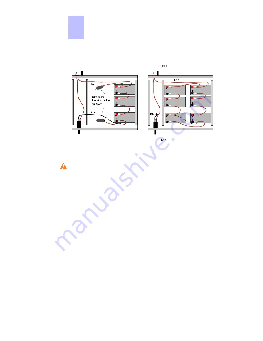
Figure 4.24: Wiring Diagram of a 12V External Battery Rack Unit (2 or 3x7Ah in parallel)
Figure 4.25: Wiring Diagram of a 36V External Battery Rack Unit (1 or 2x7Ah in parallel)
This type of unit is only used for an OmniPCX Office RCE Large platform.
Procedure
Position the 12V - 7Ah external batteries in the battery rack unit (maximum 3 batteries for an
OmniPCX Office RCE Medium platform and 6 batteries for an OmniPCX Office RCE Large
platform).
1. Open the external battery unit and position the batteries vertically in the unit.
2. Make all the connections after having removed, if necessary, the insulation devices from
the connectors that are used.
3. Place the batteries flat in the unit and close it.
4. Turn off the switch, and check the battery voltage directly on the connector at the rear of
the unit.
Preparing an External Battery Unit (stack Version)
Before starting the installation, note that:
-
External batteries must be of the same type, must be supplied by the same manufacturer
and be from the same batch run.
-
Batteries must be charged prior to installation.
Procedure for 12 V stack version (for OmniPCX Office RCE Small and OmniPCX Office
RCE Medium platforms)
The 12 V stack version of the external battery unit can be used with OmniPCX Office RCE
Small and OmniPCX Office RCE Medium platforms. It uses 12V - 7Ah batteries. Either one
battery or three batteries can be installed in the unit.
1. Ensure that the ON/OFF switch on the external battery unit is set to the OFF position (0 or
Chapter
4
( )
4-22
Summary of Contents for OmniPCX Office
Page 1: ...Installation Manual Release 9 0 October 2012 ...
Page 8: ... P 8 6 Q 8 7 R 8 7 S 8 8 T 8 8 U 8 9 V 8 9 W 8 9 0 6 ...
Page 14: ...Chapter 1 1 6 ...
Page 19: ...2 3 Installation 2 3 1 Overview ___change begin___ 2 5 ...
Page 48: ...Chapter 3 3 18 ...
Page 176: ...Chapter 4 4 128 ...
Page 178: ...Figure 5 1 Virtual Key Functions for Operator Sets in KeySystem mode Chapter 5 5 2 ...
Page 179: ...Figure 5 2 Virtual Key Functions for Manager Assistant Normal sets in KeySystem Mode 5 3 ...
Page 181: ...Figure 5 4 Virtual and Physical Add on Key Functions for Attendant Sets in KeySystem mode 5 5 ...
Page 182: ...Figure 5 5 US only Virtual Key Functions for Operator Sets in KeySystem Mode Chapter 5 5 6 ...
Page 183: ...Figure 5 6 US only Virtual Key Functions for Manager Assistant Sets in KeySystem Mode 5 7 ...
Page 184: ...Figure 5 7 US only Virtual Key Functions for Normal Sets in KeySystem Mode Chapter 5 5 8 ...
Page 185: ...Figure 5 8 Virtual Key Functions for Operator Manager Assistant Normal Sets in PABX Mode 5 9 ...
Page 186: ...Figure 5 9 US only Virtual Key Functions for Operator Sets in PABX Mode Chapter 5 5 10 ...
Page 187: ...Figure 5 10 US only Virtual Key Functions for Manager Assistant Sets in PABX Mode 5 11 ...
Page 190: ...Chapter 5 5 14 ...
Page 213: ...settings are overwritten when configured PBXs are added to a network 6 23 ...
Page 214: ...Chapter 6 6 24 ...
Page 220: ...Chapter 7 7 6 ...


