background image

Npaq MR Hardware Manual

Warranty and Field Service

Rush Service

At times, the buyer may desire to expedite a repair. Regardless of warranty or out-of-warranty status, the
buyer must issue a valid purchase order to cover the added rush service cost. Rush service is subject to
Aerotech's approval.

On-site Warranty Repair

If an Aerotech product cannot be made functional by telephone assistance or by sending and having the
customer install replacement parts, and cannot be returned to the Aerotech service center for repair, and if
Aerotech determines the problem could be warranty-related, then the following policy applies:

Aerotech will provide an on-site Field Service Representative in a reasonable amount of time, provided
that the customer issues a valid purchase order to Aerotech covering all transportation and subsistence
costs. For warranty field repairs, the customer will not be charged for the cost of labor and material. If
service is rendered at times other than normal work periods, then special rates apply.

If during the on-site repair it is determined the problem is not warranty related, then the terms and
conditions stated in the following “On-Site Non-Warranty Repair” section apply.

On-site Non-Warranty Repair

If any Aerotech product cannot be made functional by telephone assistance or purchased replacement parts,
and cannot be returned to the Aerotech service center for repair, then the following field service policy
applies:

Aerotech will provide an on-site Field Service Representative in a reasonable amount of time, provided
that the customer issues a valid purchase order to Aerotech covering all transportation and subsistence
costs and the prevailing labor cost, including travel time, necessary to complete the repair.

Service Locations

http://www.aerotech.com/contact-sales.aspx?mapState=showMap

USA, CANADA, MEXICO

CHINA

GERMANY

Aerotech, Inc.

Aerotech China

Aerotech Germany

Global Headquarters

Full-Service Subsidiary

Full-Service Subsidiary

Phone: +1-412-967-6440

Phone: +86 (21) 3319 7715

Phone: +49 (0)911 967 9370

Fax: +1-412-967-6870

Fax: +49 (0)911 967 93720

JAPAN

TAIWAN

UNITED KINGDOM

Aerotech Japan

Aerotech Taiwan

Aerotech United Kingdom

Full-Service Subsidiary

Full-Service Subsidiary

Full-Service Subsidiary

Phone: +81 (0)50 5830 6814

Phone: +886 (0)2 8751 6690

Phone: +44 (0)1256 855055

Fax: +81 (0)43 306 3773

Fax: +44 (0)1256 855649

Have your customer order number ready before calling.

64

Appendix A

www.aerotech.com

Summary of Contents for NPAQ MR

Page 1: ...on 1 06 00 Npaq MR Hardware Manual AEROTECH COM ON OFF Npaq MR FEEDBACK COMMUNICATIONS 1 2 3 4 5 6 7 8 1 2 3 4 5 6 7 8 1 2 3 4 5 6 7 8 1 2 3 4 5 6 7 8 EXT DRIVE RS232 AUX ENCODER JOYSTICK ESTOP MOTOR...

Page 2: ...ice aerotech com 101 Zeta Drive Pittsburgh PA 15238 2897 www aerotech com United Kingdom Japan Phone 44 0 1256 855055 Fax 44 0 1256 855649 Email service aerotech co uk Phone 81 0 50 5830 6814 Fax 81 0...

Page 3: ...1 Powered Motor Phasing 20 2 3 1 2 Unpowered Motor and Feedback Phasing 21 2 3 2 DC Brush Motor Connections 22 2 3 2 1 DC Brush Motor Phasing 22 2 3 3 Stepper Motor Connections 23 2 3 3 1 Stepper Moto...

Page 4: ...1 Emergency Stop ESTOP1 2 3 52 3 2 Joystick Interface 56 Chapter 4 Maintenance 59 4 1 Power Board Assembly 60 4 2 Preventative Maintenance 61 Appendix A Warranty and Field Service 63 Appendix B Revis...

Page 5: ...Figure 2 15 Analog Encoder Signals 28 Figure 2 16 Encoder Phasing Reference Diagram Standard 29 Figure 2 17 Position Feedback in the Diagnostic Display 30 Figure 2 18 Hall Effect Inputs 31 Figure 2 19...

Page 6: ...Pin Assignment 36 Table 2 16 Relay Specifications 36 Table 2 17 Differential Analog Input 0 Specifications 37 Table 2 18 Differential Analog Input 0 Pin Assignment 37 Table 2 19 Digital Analog IO Con...

Page 7: ...tive s 2014 35 EU Low Voltage Directive LVD 2006 42 EC Machinery Directive 2011 65 EU RoHS 2 Directive and has been designed to be in conformity with the applicable requirements of the following docum...

Page 8: ...rive Racks have been tested and found to be in accordance to the following listed Agency Approvals Approval Certification CUS NRTL Approving Agency TUV SUD America Inc Certificate U8 13 10 68995 012 F...

Page 9: ...disconnect any electrical components or connecting cables while connected to a power source 9 All components must be properly grounded in accordance with local electrical safety requirements 10 Opera...

Page 10: ...Npaq MR Hardware Manual Electrical Safety x www aerotech com This page intentionally left blank...

Page 11: ...JOYSTICK ESTOP MOTOR DIGITAL ANALOG IO FEEDBACK 1 2 3 4 1 2 3 4 1 2 3 4 1 2 3 4 EXT DRIVE RS232 AUX ENCODER JOYSTICK ESTOP MOTOR DIGITAL ANALOG IO COMMUNICATIONS PC Connection Motor Feedback 4 2 Motor...

Page 12: ...Npaq MR Hardware Manual Quick Installation Guide xii www aerotech com This page intentionally left blank...

Page 13: ...log input one analog output and a single axis Position Synchronized Output PSO signal Other features and options available with the MR drive chassis include an external joystick connection port integr...

Page 14: ...analog input 10 V l One fail safe brake or user relay output l 8 optically isolated logic inputs 5 24 VDC may be connected in current sourcing or sinking mode l 8 optically isolated logic outputs 5 2...

Page 15: ...1 MOTOR FEEDBACK up to x8 CW CCW Home Limits Encoder Fault Hall A B C Motor Over Temperature MOTOR OUTPUT up to x8 Amplifier Control Power Motor Power ESTOP AC Power Input Amplifier Heatsink Over Temp...

Page 16: ...ns 4 Axis 8 Axis Unipolar Bipolar Unipolar Bipolar 40 LP 300W 10B 400W 40LP 500W 10B 400W 80 LP 300W 20B 500W 40LP 500W 20B 500W 40 600W 30B 500W 40LP 1000W 30B 500W 80 600W 40B 600W 40LP 1000W 40B 10...

Page 17: ...Current 5 A Power Amplifier Bandwidth 2500 Hz maximum software selectable Power Amplifier Efficiency 85 95 2 PWM Switching Frequency 20 kHz Minimum Load Inductance 0 1 mH 80 VDC User Power Supply Outp...

Page 18: ...nt 2 5 Power Amplifier Bandwidth 2500 Hz maximum software selectable Minimum Load Resistance 0 5 Output Impedance 0 2 each phase User Power Supply Output 5 VDC 500 mA Modes of Operation Brushless Brus...

Page 19: ...used in the following equations Brushless Motor Output Power Rotary Motors Pout W Torque N m Angular velocity rad sec Linear Motors Pout W Force N Linear velocity m sec Rotary or Linear Motors Pout W...

Page 20: ...ections and cables W A R N I N G Use both handles to lift and carry the Npaq MR AEROTECH COM ON OFF Npaq MR FEEDBACK 1 2 3 4 1 2 3 4 1 2 3 4 1 2 3 4 EXT DRIVE RS232 AUX ENCODER JOYSTICK ESTOP MOTOR DI...

Page 21: ...4 9 16 93 492 5 19 39 41 7 1 64 566 1 22 29 132 5 5 22 57 2 2 25 37 7 1 48 7 1 0 28 4 pls 482 6 19 00 8 3 0 33 TYP 465 9 18 34 444 5 17 50 Drawing Number 620E1408 Dimensions MM IN Figure 1 4 Dimension...

Page 22: ...20 to 70 C 4 to 158 F Humidity Maximum relative humidity is 80 for temperatures up to 31 C Decreasing linearly to 50 relative humidity at 40 C Non condensing Altitude Up to 2000 meters Pollution Poll...

Page 23: ...ast Software Version HEX RC 2 14 Current Ndrive CL 2 18 5 02 A 2 55 5 02 Ndrive CP 2 03 2 55 A 2 10 Current B 2 19 Current Ndrive FLS 4 03 Current Ndrive FLS A 4 06 001 Current Ndrive HL 1 01 2 55 Ndr...

Page 24: ...Npaq MR Hardware Manual Introduction 12 Chapter 1 www aerotech com This page intentionally left blank...

Page 25: ...tem or its components A documentation package is provided with the Npaq MR either in a large manilla envelope or on the installation device containing manuals interconnection drawings and other docume...

Page 26: ...e 2 1 Power and Control Connections AEROTECH COM ON OFF Npaq MR Power Switch Circuit Breaker Figure 2 2 Power Switch All low voltage connections must be made using cables wires sized for the maximum c...

Page 27: ...uirements for the Npaq MR drive chassis are listed in Table 2 1 Table 2 1 Main AC Power Input Voltages and Current Requirements AC Input Voltage Input Amps maximum continuous 100 VAC 50 60 Hz 10 A 115...

Page 28: ...tegrated with other electronics EMC testing must be conducted on the final product configuration The Npaq MR can generate conducted AC line and radiated noise when configured with MP drives Minimize c...

Page 29: ...point Table 2 4 AC Power Wiring Specifications Connection Specification Value Signal Wiring Cable Wire Rating 1 300 V Minimum Current Capacity 25 A Temperature Rating Insulation 2 80 C Low Voltage Pow...

Page 30: ...E RS232 AUX ENCODER JOYSTICK ESTOP MOTOR DIGITAL ANALOG IO 1 2 3 4 5 Motor Output Figure 2 4 Motor Output Connections Table 2 5 Motor Power Output Connector Pin Assignment Pin Description Wire Size 1...

Page 31: ...motor phasing adjustments are not required and this section may be skipped The controller requires that the Back EMF of each motor phase be aligned with the corresponding Hall effect signal To ensure...

Page 32: ...ion Manager for motor Hall and encoder phasing Feedback Monitoring The state of the encoder and Hall effect device signals can be observed in the Status Utility An L for the given Hall input indicates...

Page 33: ...B Motor Lead 2 C Power Supply TP3 TP2 TP1 TP6 TP7 Hall 1 Hall 2 Hall 3 CHANNEL 1 CHANNEL 2 Figure 2 7 Motor Phasing Oscilloscope Example With the designations of the motor and Hall leads of a third p...

Page 34: ...d motor 1 Connect the positive lead of the voltmeter to the one of the motor terminals 2 Connect the negative lead of the voltmeter to the other motor terminal 3 Rotate the motor clockwise by hand Mot...

Page 35: ...tor can be run with or without an encoder If an encoder is not being used phasing is not necessary With an encoder test for proper motor phasing by running a positive motion command If there is a posi...

Page 36: ...B brushless motors only Input 6 Encoder Marker Reference Pulse Input 7 Encoder Marker Reference Pulse Input 8 Analog Input 0 Input 9 Reserved N A 10 Hall Effect Sensor A brushless motors only Input 1...

Page 37: ...encoder feedback phasing Refer to Section 2 6 for the auxiliary encoder channel N OTE Encoder wiring should be physically isolated from motor AC power and all other power wiring N OTE The PSO feature...

Page 38: ...g signals will cause a feedback fault when the axis is enabled An analog encoder is used with the MXH MXU option refer to Section 2 4 1 2 for more information Table 2 9 Encoder Specifications Specific...

Page 39: ...ncoder interface pin assignment is indicated in Section 2 4 1 The gain offset and phase balance of the analog Sine and Cosine encoder input signals can all be adjusted via controller parameters Encode...

Page 40: ...Npaq MR Hardware Manual Installation and Configuration Figure 2 15 Analog Encoder Signals 28 Chapter 2 www aerotech com...

Page 41: ...Feedback to count more negative swap the connections to the controllers SIN and the SIN N encoder inputs For dual loop systems the velocity feedback encoder is displayed in the diagnostic display Figu...

Page 42: ...Npaq MR Hardware Manual Installation and Configuration Figure 2 17 Position Feedback in the Diagnostic Display 30 Chapter 2 www aerotech com...

Page 43: ...ll generate a Hall Fault axis fault Refer to Section 2 3 1 1 for Hall effect device phasing Table 2 11 Hall Effect Feedback Pin Assignment Pin Description In Out Bi 1 Chassis Frame Ground N A 3 5V Pow...

Page 44: ...rating conditions the resistance of the thermistor is low i e 100 ohms which will result in a low input signal As the increasing temperature causes the thermistor s resistance to increase the signal w...

Page 45: ...ult output Some manufacturers use this signal to indicate a loss of encoder function typically forcing an axis to immediately disable This signal is parameter configurable Table 2 13 Encoder Fault Pin...

Page 46: ...of travel limit input The Home Limit switch can be parameter configured for use during the home cycle however the CW or CCW EOT limit is typically used instead Table 2 14 End of Travel Limit Inputs P...

Page 47: ...l be able to move further into a limit but be unable to move out To correct this swap the connections to the CW and CCW inputs at the motor feedback connector The logic level of the EOT limit inputs m...

Page 48: ...brake is configured for automatic or manual control using controller parameters refer to the A3200 Help file for more information Table 2 15 Brake Output Pin Assignment Pin Description In Out Bi 13 O...

Page 49: ...re 2 23 Table 2 17 Differential Analog Input 0 Specifications Specification MP Drive Value ML Drive Value AI AI 10 V to 10 V 10 V to 10 V Input Impedance 1 M each input to ground 1 M each input to gro...

Page 50: ...Isolated Input 1 Input 7 Optically Isolated Input 2 Input 8 Optically Isolated Input 3 Input 9 Output Common Input 10 Optically Isolated Output 0 Output 11 Optically Isolated Output 1 Output 12 Optic...

Page 51: ...igure 2 24 Table 2 20 Analog Input 1 Specifications Specification MP Drive Value ML Drive Value AI AI 10 V to 10 V 10 V to 10 V Input Impedance 1 M each input to ground 1 M each input to ground Resolu...

Page 52: ...does not have an Analog Output 0 Table 2 22 Analog Output Specifications TB102 B Specification Value Output Voltage 5 V to 5 V Output Current 5 mA Resolution bits 16 bits Resolution volts 153 V Table...

Page 53: ...ion In Out Bi 9 Output Common Input 10 Optically Isolated Output 0 Output 11 Optically Isolated Output 1 Output 12 Optically Isolated Output 2 Output 13 Optically Isolated Output 3 Output 21 Output Co...

Page 54: ...imize glitching OP 5 24 VDC OPTOOUT1 OPTOOUT2 OPTOOUT3 OM Figure 2 26 Outputs Connected in Current Sourcing Mode 2 1 3 PIN 10 PIN 9 LOAD LOAD LOAD LOAD PIN 11 PIN 12 PIN 13 PIN 21 OPTOOUT0 Electronic...

Page 55: ...connections can be directly connected to the drive s power supply however doing so will effectively defeat the isolation and will reduce noise immunity Table 2 26 Digital Input Specifications Input V...

Page 56: ...s 4 7 not shown OPTOIN1 OPTOIN2 OPTOIN3 Input Switches Figure 2 28 Inputs Connected to a Current Sourcing Device PIN 5 PIN 4 OPTOIN COMMON 1 5 24 VDC OPTOIN0 Opto Inputs 4 7 not shown OPTOIN1 OPTOIN2...

Page 57: ...he IO option has been ordered for the axis Table 2 28 Aux Encoder Specifications Specification Value Voltage 5 VDC Encoder Frequency 10 MHz maximum 25 nsec minimum edge separation x4 Quadrature Decodi...

Page 58: ...IN 8 PIN 6 PIN 7 PIN 2 AUXSIN AUXMRK AUXMRK AUXSIN AUXCOS 180 180 180 5V 5V 5V ADM1485 ADM1485 ENCODER FAULT DETECTION ADM1485 AUXCOS Terminating resistors are not present when configured as an output...

Page 59: ...frequency pulse transmission is required It is best to locate the line receiver or opto isolator close to the receiving electronics N OTE The PSO feature is not compatible with the MXU option The PSO...

Page 60: ...tput shown Opposite polarity available by reversing connections to Pins 3 and 8 Aux Marker 120 180 typical 10 mA 180 Differential 5 VDC Isolated Section vcc To Laser Active Low Output HCPL 2601 or 6N1...

Page 61: ...2 port NFIRE PCI TI LP Low Profile OHCI compliant PCI NFIRE PCIE GOF FireWire PCIE X1 Glass Optical Fiber Board Table 2 32 FireWire Repeaters for cables exceeding 4 5 m 15 ft specification Part Numbe...

Page 62: ...nd Configuration 2 8 PC Configuration and Operation Information For additional information about PC configuration hardware requirements programming utilities and system operation refer to the A3200 He...

Page 63: ...ction 3 1 Emergency Stop ESTOP1 2 3 ESTOP Sense Input EN ISO 13849 1 Category 2 Category 3 MXU Section 2 4 1 2 Analog Encoder Interface Encoder Resolution Multiplier up to 1 024 times 200 kHz 2 MHz ma...

Page 64: ...IO ESTOP 1 8 9 15 Figure 3 1 ESTOP Option Interface Table 3 2 ESTOP Option Mating Connector Mating Connector Aerotech P N Third Party P N 15 Pin D Connector ECK00100 FCI DA15P064TXLF Backshell ECK010...

Page 65: ...r Aerotech ECW01107 Sprecher Schuh CA7 16E M31 24E AC 1 resistive load Rating of 32 A Turn On The coil requires 17 0 W to turn on which is equal to 700 mA 24 V On Holding The coil requires 1 7 W on ho...

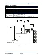
Page 66: ...6 3 4 1 24 DC POWER SUPPLY SOFT START BOARD DRIVE ASSEMBLY CR1 CR2 CR1 CR2 CR2 CR1 CR2 CR1 15 PIN MALE D ECK00100 BACKSHELL ECK01022 15 PIN FEMALE D ECK00326 JACKSOCKET ECK00328 RESET COM ESTOP OPTO...

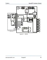
Page 67: ...4 1 9 10 7 8 2 5 6 3 4 1 24 DC POWER SUPPLY SOFT START BOARD DRIVE ASSEMBLY CR1 CR2 CR1 CR2 CR2 CR1 CR2 CR1 15 PIN MALE D ECK00100 BACKSHELL ECK01022 15 PIN FEMALE D ECK00326 JACKSOCKET ECK00328 RESET...

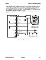
Page 68: ...TOP MOTOR DIGITAL ANALOG IO Joystick 1 8 9 15 Figure 3 5 Joystick Interface Table 3 5 Joystick Interface Connector Pin Assignment Pin Label Description In Out Bi 1 5V 5V power Output 2 JSA Joystick bu...

Page 69: ...rovided they produce a symmetric output voltage within the range of 10V to 10V All joystick operating parameters are software configurable Refer to the A3200 Help file for additional information AEROT...

Page 70: ...Npaq MR Hardware Manual Options 58 Chapter 3 www aerotech com This page intentionally left blank...

Page 71: ...the drive D A N G E R Always disconnect the Mains power connection before opening the Npaq MR chassis D A N G E R Before performing any tests be aware of lethal voltages inside the controller and at...

Page 72: ...power applied to unit Board Assembly Drawing Number 690D1645 Rev 1 BW6 BW4 TB5 1 J1 DS1 1 TB3 1 TB4 1 TB6 1 TB1 1 TB2 B A S2 MATE ECK00213 MATE ECK01577 MATE ECK00213 MATE ECK01577 MATE ECK01577 MATE...

Page 73: ...eck for fluids or electrically conductive material exposure Any fluids or electrically conductive material must not be permitted to enter the Npaq MR Visually inspect all cables and connections Tighte...

Page 74: ...Npaq MR Hardware Manual Maintenance 62 Chapter 4 www aerotech com This page intentionally left blank...

Page 75: ...ut such approval A Return Materials Authorization RMA number must accompany any returned product s The RMA number may be obtained by calling an Aerotech service center or by submitting the appropriate...

Page 76: ...s and conditions stated in the following On Site Non Warranty Repair section apply On site Non Warranty Repair If any Aerotech product cannot be made functional by telephone assistance or purchased re...

Page 77: ...section updated Section 2 5 1 l Opto Isolated Inputs section updated Section 2 5 4 l Opto Isolated Outputs section updated Section 2 5 3 l Aux Encoder section updated Section 2 6 l PSO Laser Firing S...

Page 78: ...Npaq MR Hardware Manual Revision History 66 Appendix B www aerotech com This page intentionally left blank...

Page 79: ...urrent specifications 5 6 Control Supply specifications 5 6 D DC Brush Motor Connections 22 DC Brush Motor Phasing 22 Declaration of Conformity vii Digital Analog IO Connections 38 dimensions 8 Drive...

Page 80: ...Feedback Connector Pin Assignment 24 Motor Output Connections 18 Motor Phasing Oscilloscope Example 21 Motor Power Output Connections 18 Motor Power Output Mating Connector 18 Motor Supply specificat...

Page 81: ...trical Specifications 5 Solid State Relay Rating 36 Stepper Motor Connections 23 Stepper Motor Phasing 23 T Thermistor Input 32 U UFM ST 16 unit weight 9 Unpacking the Chassis 13 Unpowered Motor and F...

Page 82: ...Npaq MR Hardware Manual Index 70 www aerotech com This page intentionally left blank...

Reviews: