Quick Installation Guide
Npaq MR Hardware Manual
Quick Installation Guide
This chapter describes the order in which connections and settings should typically be made to the Npaq
MR. If a custom interconnection drawing was created for your system (look for a line item on your Sales
Order under the heading “Integration”), that drawing can be found on your installation device.
There are four standard connections that must be made to the Npaq MR.
FEEDBACK
COMMUNICATIONS
1
2
3
4
5
6
7
8
1
2
3
4
5
6
7
8
1
2
3
4
5
6
7
8
1
2
3
4
5
6
7
8
EXT DRIVE
RS232
AUX ENCODER
JOYSTICK
ESTOP
MOTOR
DIGITAL / ANALOG IO
FEEDBACK
1
2
3
4
1
2
3
4
1
2
3
4
1
2
3
4
EX
T
D
R
IVE
R
S2
3
2
AUX ENCODER
JOYSTICK
ESTOP
MOTOR
DIGITAL / ANALOG IO
C
O
MM
U
N
IC
A
T
IO
N
S
PC Connection
Motor Feedback
4
2
Motor Power
3
PC Connection
Motor Feedback
4
2
Motor Power
3
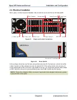
Connect the power source to the AC Power input
8 Axis Model
4 Axis Model
1
Connect the Motors to the Motor Power inputs
4 Connect the Motors to the Motor Feedback inputs
2 Connect the PC
3
AC Power
1
AC Power
1
Figure 1:
Quick Start Connections
Quick Start Summary
Topic
Section
AC Power
Section 2.2.1. AC Power Connections
PC Communication
Section 2.7. Communications Connector
Motor Power
Section 2.3. Motor Output Connections
Motor Feedback
Section 2.4. Motor Feedback Connections
www.aerotech.com
xi


