Npaq MR Hardware Manual
Options
3.1. Emergency Stop (ESTOP1,2,3)
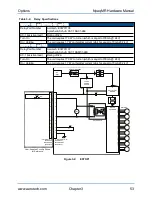
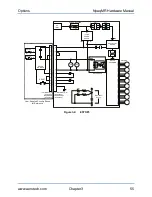
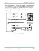
ESTOP1, 2, and 3 are integrated emergency stop hardware options available on the Npaq MR. User
connections are made via the optional 15D ESTOP connector.
l
ESTOP1 uses a single relay to disconnect the motor power supply from the internal drive modules.
l
ESTOP2 uses two relays in series to disconnect the motor power supply from the drive modules.
l
ESTOP3 uses two relays in series to disconnect the motor power supply from the drive modules and
dissipates the stored energy in the motor power supply.
All relays are force guided and have a monitor contact.
FEEDBACK
COMMUNICATIONS
1
2
3
4
5
6
7
8
1
2
3
4
5
6
7
8
1
2
3
4
5
6
7
8
1
2
3
4
5
6
7
8
EXT DRIVE
RS232
AUX ENCODER
JOYSTICK
ESTOP
MOTOR
DIGITAL / ANALOG IO
ESTOP
1
8
9
15
Figure 3-1:
ESTOP Option Interface
Table 3-2:
ESTOP Option Mating Connector
Mating Connector
Aerotech P/N
Third Party P/N
15-Pin D-Connector
ECK00100
FCI DA15P064TXLF
Backshell
ECK01022
Amphenol 17E-1725-2
The ESTOP1,2,3 options can be used to provide performance in accordance with EN ISO 13849-1 as shown
in
.
Table 3-3:
ESTOP Safety Ratings
Option
Relays
EN ISO 13849-1
ESTOP1
1 force guided relay with monitor contact
Category 2, PL d
ESTOP2
2 force guided relays with monitor contacts
Category 3, PL d
ESTOP3
2 force guided relays with monitor contracts
Category 3, PL d
W A R N I N G : The machine integrator, OEM, or end user is responsible for performing the
design, integration, and test of the safety system in accordance with the relevant safety
standards. This responsibility includes the use of safety monitoring devices, interlocks,
switches, light curtains and all other means of providing operator protection.
52
Chapter 3
www.aerotech.com

