Npaq MR Hardware Manual
Options
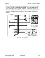
3.2. Joystick Interface
The Joystick Interface is an optional 15-pin ‘D’ style connector accessible at the rear of the Npaq MR
chassis. The joystick option is factory wired to a specified axis' I/O option board. The Joystick Interface
uses two analog inputs and three dedicated inputs (joystick buttons). IO signals not used by the joystick are
not available to the user. Joystick electrical connections are shown in
FEEDBACK
COMMUNICATIONS
1
2
3
4
5
6
7
8
1
2
3
4
5
6
7
8
1
2
3
4
5
6
7
8
1
2
3
4
5
6
7
8
EXT DRIVE
RS232
AUX ENCODER
JOYSTICK
ESTOP
MOTOR
DIGITAL / ANALOG IO
Joystick
1
8
9
15
Figure 3-5:
Joystick Interface
Table 3-5:
Joystick Interface Connector Pin Assignment
Pin #
Label
Description
In/Out/Bi
1
+5V
+5V power
Output
2
JSA
Joystick button A (Input 5) Axis Select
Input
3
JOY X
Analog Input 0
Input
4
Common
Joystick power common
N/A
5
Not Used
Not Used
N/A
6
JOY Y
Analog Input 1
Input
7
JS B
Joystick button B (Input 6) Speed Select
Input
8
Not Used
Not Used
N/A
9
Not Used
Not Used
N/A
10
Not Used
Not Used
N/A
11
Not Used
Not Used
N/A
12
Shield
Shield
N/A
13
Interlock
Joystick Interlock (Input 7)
Input
14
Not Used
Not Used
N/A
15
Not Used
Not Used
N/A
Mating Connector
Aerotech P/N
Third Party P/N
15-Pin D-Connector
ECK00100
FCI DA15P064TXLF
Backshell
ECK01022
Amphenol 17E-1725-2
56
Chapter 3
www.aerotech.com


