Interfaces
31
Q7-BASE
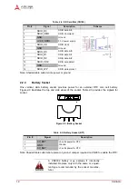
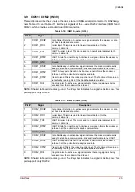
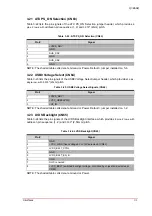
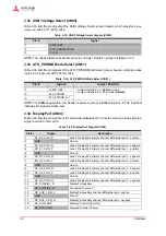
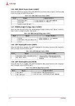
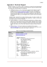
3.21 ATX PS_ON Selection (CN63)
Table 3-22 lists the pin signals of the ATX PS_ON Selection jumper header, which provides
6
pins, 2 rows, with
odd/even pin sequence (1, 2) and
0.079
" (2mm) pitch.
NOTE: The shaded table cells denote Ground or Power. Default = jumper installed on 5-6
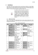
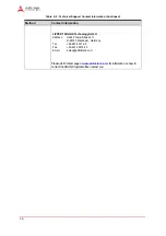
3.22 USB0 Voltage Select (CN64)
Table 3-23 lists the pin signals of the USB0 Voltage Select jumper header, which provides
3 pins,
single-row, with 0.079
" (2mm) pitch.
NOTE: The shaded table cells denote Ground or Power. Default = jumper installed on 1-2.
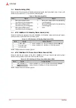
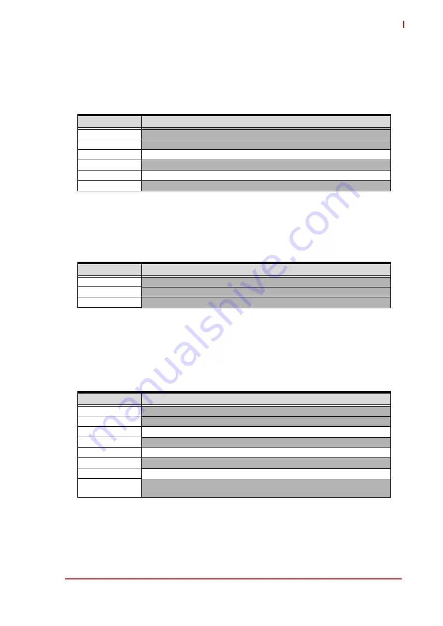
3.23 LVDS Backlight (CN65)
Table 3-24 lists the pin signals of the LVDS Backlight interface, which provides
8 pins, 2 rows, with
odd/even pin sequence (1, 2) and
0.100
" (2.54mm) pitch.
NOTE: The shaded table cells denote Ground or Power.
Table 3-22: ATX PS_ON Selection (CN63)
Pin #
Signal
1
+V5P0_SBY
2
GND
3
SUS_S3#
4
GND
5
SUS_S5#
6
GND
Table 3-23: USB0 Voltage Select Signals (CN64)
Pin #
Signal
1
+V5P0_SBY
2
+VCC_USB02PWR
3
+V5_IN
Table 3-24: LVDS Backlight (CN65)
Pin #
Signal
1
GND
2
+VCC_LVDS (fixed voltage 5V or 12V selected at CN62)
3
LVDS_BKLT_CTRL
4
GND
5
LVDS_BKLT_EN_B
6
GND
7
Not Connected
8
+VCC_BKLT (switched backlight voltage, controlled by chipset and selected at
CN59)


