34
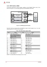
Interfaces
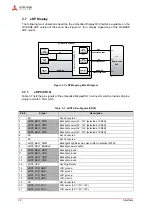
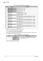
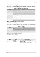
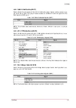
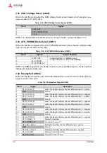
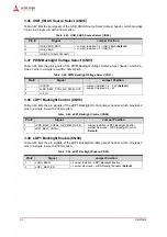
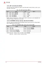
3.27 LPT Interface (CN71)
Table 3-28 lists the pin signals of the LPT Interface header, which provides 26
pins, 2 rows, with
odd/even sequence (1, 2) and 0.100
"
(2.54mm)
pitch.
NOTE: The shaded table cells denote Ground or Power. The # symbol indicates the signal is
Active Low.
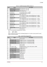
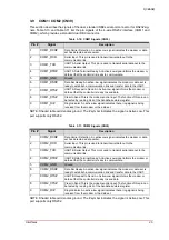
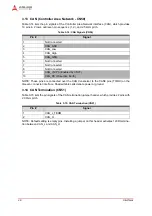
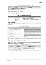
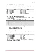
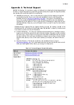
3.28 System Interface (CN73)
Table 3-29 lists the pin signals of the System Interface header, which provides 20
pins, 2 rows,
with odd/even sequence (1, 2) and 0.100
"
(2.54mm)
pitch.
NOTE: The shaded table cells denote Ground. The # symbol indicates the signal is Active Low.
Table 3-28: LPT Interface Signals (CN71)
Pin #
Signal
Pin #
Signal
1
LPT_STB#_R
2
LPT_AFD#_R
3
LPT_PD0_R
4
LPT_ERR#
5
LPT_PD1_R
6
LPT_INIT#_R
7
LPT_PD2_R
8
LPT_SLIN#_R
9
LPT_PD3_R
10
GND
11
LPT_PD4_R
12
GND
13
LPT_PD5_R
14
GND
15
LPT_PD6_R
16
GND
17
LPT_PD7_R
18
GND
19
LPT_ACK#
20
GND
21
LPT_BUSY
22
GND
23
LPT_PE
24
GND
25
LPT_SLCT
26
+VCC_LPT (+5 volts)
Table 3-29: System Interface Signals (CN73)
Pin #
Signal
Pin #
Signal
1
+V3P3_SYSCON
2
+V5P0_SYSCON
3
SMB_CLK
4
SPI_CLK
5
SMB_DATA
6
SPI_MISO
7
SMB_Q7_ALERT#
8
SPI_MOSI
9
SUS_STAT#
10
SPI_CS0#
11
GP1WIRE
12
SPI_CS1#
13
WD_TRIG#
14
THRM#
15
WD_OUT
16
THRMTRIP#
17
BIOS_DIS#
18
BATLOW#
19
GND
20
GND