


20
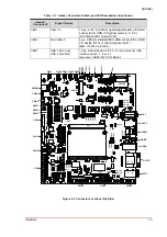
Interfaces
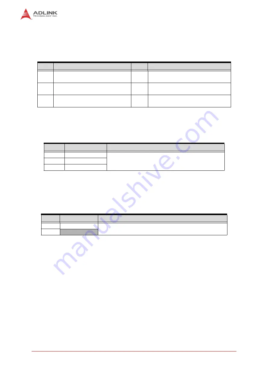
3.2
Manufacturing (CN2)
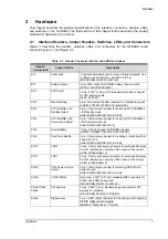
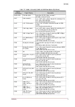
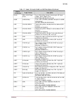
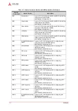
Table 3-2 lists the pin signals of the Manufacturing header, which provides 6 pins, 2 rows, with
odd/even pin sequence (1, 2) and 0.079" (2.00mm) pitch.
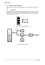
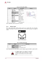
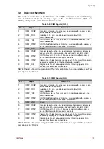
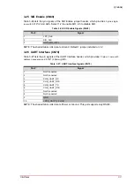
3.3
ATX / B5V Standby Mode Select (CN3)
Table 3-3 lists the pin signals of the ATX / B5V Standby mode select jumper header,
which provides 3 pins with 0.079" (2.00mm) pitch.
NOTE: Shaded table cell denotes ground.
3.4
ATX / B5V Power Good Mode Select (CN4)
Table 3-4 lists the pin signals of the ATX / B5V Power Good mode select jumper
header, which provides 2 pins with 0.079" (2.00mm) pitch.
NOTE: Shaded table cell denotes ground.
Table 3-2: Manufacturing (CN2)
Pin #
Signal
Pin #
Signal
1
MFG_NC0 (Reserved for
manufacturing and debugging)
2
MFG_NC1 (Reserved for manufacturing
and debugging)
3
MFG_NC2 (Reserved for
manufacturing and debugging)
4
MFG_NC3 (Reserved for manufacturing
and debugging)
5
MFG_NC4 (Reserved for
manufacturing and debugging)
6
GND
Table 3-3: ATX / B5V Standby Mode Select (CN3)
Pin #
Signal
Jumper Position
1
+V5P0_SBY
• Jumper Installed (1-2) - ATX +5V Standby selected (
Default
)
• Jumper Installed (2-3) - B5V Standby selected
2
5V0_SBY_OFF
3
ATX_PS_ON#
Table 3-4: ATX / B5V Power Good Mode Select (CN4)
Pin #
Signal
Jumper Position
1
ATX_PWRGD_5V
• Jumper Installed (1-2) - ATX +5V Power Good selected (
Default
)
• Jumper Removed - B5V Power Good selected
2
GND