28
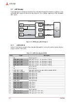
Interfaces
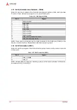
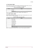
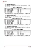
3.13 CAN (Controller Area Network - CN50)
Table 3-14 lists the pin signals of the Controller Area Network interface (CAN), which provides
10 pins in 2 rows, odd/even pin sequence (1, 2), and 2.54mm pitch.
NOTE: These pins are connected over the CAN transceiver to the CAN0 pins (TX/RX) on the
Qseven connector interface. Shaded table cells denote power or ground.
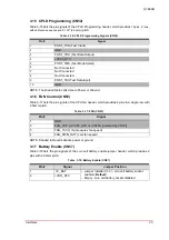
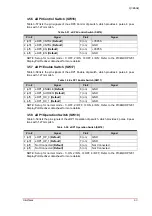
3.14 CAN Termination (CN51)
Table 3-15 lists the pin signals of the CAN termination jumper header, which provides 2 pins with
2.00mm pitch.
NOTE: Default setting is empty pins. Installing a jumper on this header activates 120R termina-
tion between CAN_L and CAN_H.
Table 3-14: CAN Signals (CN50)
Pin #
Signal
1
Not Connected
2
CAN_GND
3
CAN_Low
4
CAN_High
5
CAN_GND
6
Not Connected
7
Not Connected
8
Not Connected
9
CAN_+5VP0 (Enabled by CN77)
10
CAN_PE (Protective Earth)
Table 3-15: CAN Termination (CN51)
Pin #
Signal
1
CAN_L_TERM
2
CAN_H


