


14
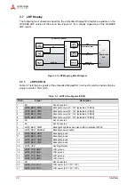
Hardware
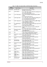
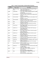
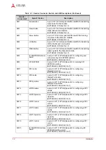
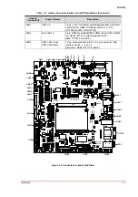
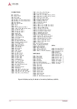
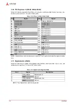
Figure 2-2: Reference Key for Headers, Connectors, Switches, and LEDs
Q7-BASE R1_B2_top_conn_refkey_a
CONNECTORS:
AJ1
- Audio Jack
BT1
- Battery Socket
CN1
- ATX Power
CN2
- Manufacturing
CN3
- BattMan / ATX Power Mode Select
CN4
- BattMan / ATX Power Mode Select
CN5
- Smart Battery
CN8
- Post Code Enable
CN10
- eDP 0
CN11
- eDP 1
CN20
- PS/2 Power Source Select
CN39
- COM1/COM2 (standard connector)
CN42
- PCI Express (slot 1)
CN44
- PCI Express (slot 2)
CN45
- PCI Express (slot 3)
CN46
- Digital Audio
CN50
- CAN Interface
CN51
- CAN Termination
CN52
- CPLD Programming
CN53
- FAN control
CN57
- Battery Termination
CN59
- Backlight Voltage Select
CN61
- Enable Keyboard Controller
CN62
- LCD Voltage Select
CN63
- ATX PS_ON Select
CN64
- USB0 Voltage Select
CN65
- LVDS Backlight
CN66
- LVDS Interface
CN69
- SIO Enable
CN70
- UART Interface
CN71
- LPT Interface
CN72
- SD/MMC 4.x Slot
CN73
- System Interface
CN74
- PCIe Mini Card Slot
CN75
- PCIe Mini Latch
CN76
- PCIe Mini Latch
CN77
- CAN Enable 5V
CN78
- LPC / TPM Interface
CN79
- FAN Power Select
CN80
- USB1 Voltage Select
CN81
- ATX_PWRGD Mode Select
CN84
- DP Interface
CN85
- Display Mode Select
CN86
- I2S Interface
CN87
- HDA_SYNC or I2S_WS Select
CN88
- HDA_RST or I2S_RST Select
CN89
- HDA_BITCLK or I2S_CLK Select
CN90
- HDA_SDO or I2S_SDO Select
CN91
- HDA_SDI or I2S_SDI Select
CN92
- EN_V3P3S Mode Select
CN93
- USB3_CN_p or USB3_mPCIe_p Select
CN94
- USB3_CN_n or USB3_mPCIe_n Select
CN95
- USB OTG Control Select
CN96
- USB_VBUS Source Select
CN97
- Backlight Voltage Select
CN98
- eDP Backlight Control
CN99
- eDP Backlight Enable
CN100
- SD Card Slot
CN101
- USB5_CN_p or USB5_20_p Select
CN102
- USB5_CN_n or USB5_20_n Select
CN103
- USB 3.0 Voltage Select
CN104
- LRESET# Source Select
CN105
- ACT/LINK LED Source Select
CN106
- ACT/LINK LED Anode Select
CN107
- 1000Mbit Anode Select
CN108
- 100Mbit Anode Select
CN109
- ATX_PWRGD Source Select
CN110
- SMB_ALERT_5V# Source Select
CN111
- SMB_CLK_5V# Source Select
CN112
- SMB_DATA_5V# Source Select
CN113
- USB 2.0 OC# Target Select
CN114
- USB 3.0 OC# Target Select
HDMI1
- HDMI Socket
PS1
- PS/2 Keyboard and Mouse
RJ451
- Gb Ethernet (Standard)
SATA0
- SATA (Standard)
SATA1
- SATA (Standard)
USB1
- USB 2.0 (Standard)
USB2
- Mini USB (Standard
USB3
- USB 3.0 / USB 2.0 (Standard)
SWITCHES:
SW1
- Reset Button
SW2
- Sleep Button
SW3
- Power Button
SW4
- LID Button
SW5
- Wake Button
SW6
- I2C EEPROM Address
SW9
- SPI EEPROM Interface Select
SW11
- DP Control
SW12
- DP Enable
SW13
- DP Operation
SW14
- eDP0 Enable
SW15
- eDP0 Operation
SW16
- eDP0 Control
SW17
- eDP1 Enable
SW18
- eDP1 Operation
SW19
- eDP1 Control
SW20
- I2C EEPROM Interface Select
LEDs:
LED1
- PCIe Mini WWAN
LED2
- PCIe Mini WLAN
LED3
- PCIe Mini WPAN
LED4
- SD/MMC
LED5
- SATA Activity
LED6
- POST 80 High
LED7
- POST 80 Low
LED8
- POST 81 High
LED9
- POST 81 Low
LED11
- S3 Suspend
LED12
- S5 Suspend
LED13
- Thermal Trip
LED14
- Watchdog


