

22
Interfaces
3.7
eDP Display
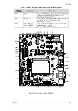
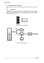
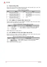
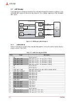
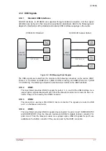
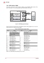
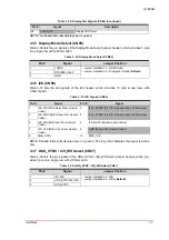
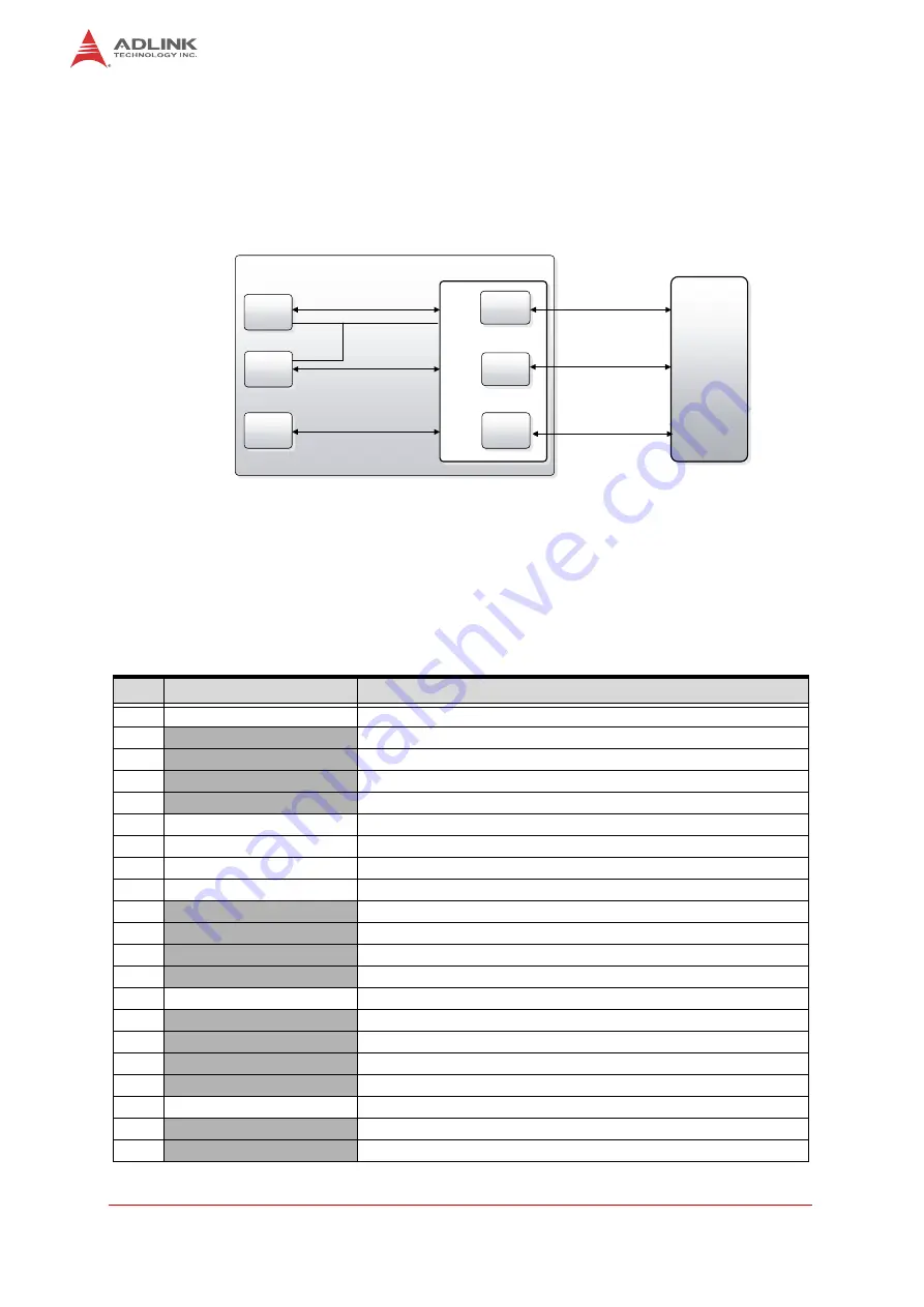
The following two subsections describe the embedded DisplayPort interface available on the
Q7-BASE eDP version of the board. See Figure 3-1 for a display signal map of the Q7-BASE
eDP model.
Figure 3-1: eDP Mapping Block Diagram
3.7.1
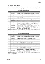
eDP0 (CN10)
Table 3-7 lists the pin signals of the embedded DisplayPort 0 connector, which provides 40-pins,
single row with 0.5mm pitch.
Table 3-7: eDP0 Video Signals (CN10)
Pin #
Signal
Description
1
NC
Not Connected
2
eDP0_BKLT_PWR
Backlight power (5V / 12V [selected at CN59])
3
eDP0_BKLT_PWR
Backlight power (5V / 12V [selected at CN59])
4
eDP0_BKLT_PWR
Backlight power (5V / 12V [selected at CN59])
5
eDP0_BKLT_PWR
Backlight power (5V / 12V [selected at CN59])
6
NC
Not Connected
7
NC
Not Connected
8
eDP0_BKLT_PWM
Backlight brightness via pulse width modulation (PWM)
9
eDP0_BKLT_ENABLE
Backlight power enable
10
eDP0_BKLT_GND
Backlight ground
11
eDP0_BKLT_GND
Backlight ground
12
eDP0_BKLT_GND
Backlight ground
13
eDP0_BKLT_GND
Backlight ground
14
eDP0_HPD
Hot Plug Detect
15
eDP0_LCD_GND
LCD ground
16
eDP0_LCD_GND
LCD ground
17
eDP0_LCD_GND
LCD ground
18
eDP0_LCD_GND
LCD ground
19
NC
Not Connected
20
eDP0_LCD_VCC
LCD power (3.3V / 5V / 12V)
21
eDP0_LCD_VCC
LCD power (3.3V / 5V / 12V)
40pin
eDP
connector
40pin
eDP
connector
HDMI or
DP
Con
n
e
ct
o
r (
M
X
M
2)
Intel®
Apollo Lake
SoC
HDMI/DP
3840x2160@30Hz
LVDS
Primary
Channel
LVDS
Secondary
Channel
HDMI/DP
DP
4096x2160@60Hz
DDI
DDI
Q7-BASE (eDP op
Ɵ
on)
eDP
HDMI/DP
DDI
BLK
eDP
4096x2160@60Hz
eDP/DP
BLK