
24
Interfaces
NOTE: The shaded table cells denote power or ground.
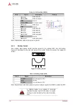
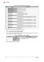
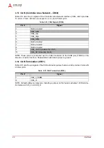
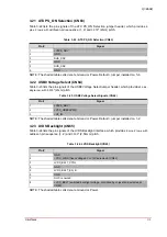
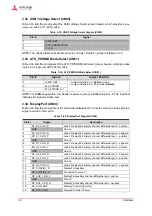
3.8
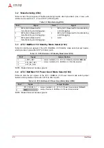
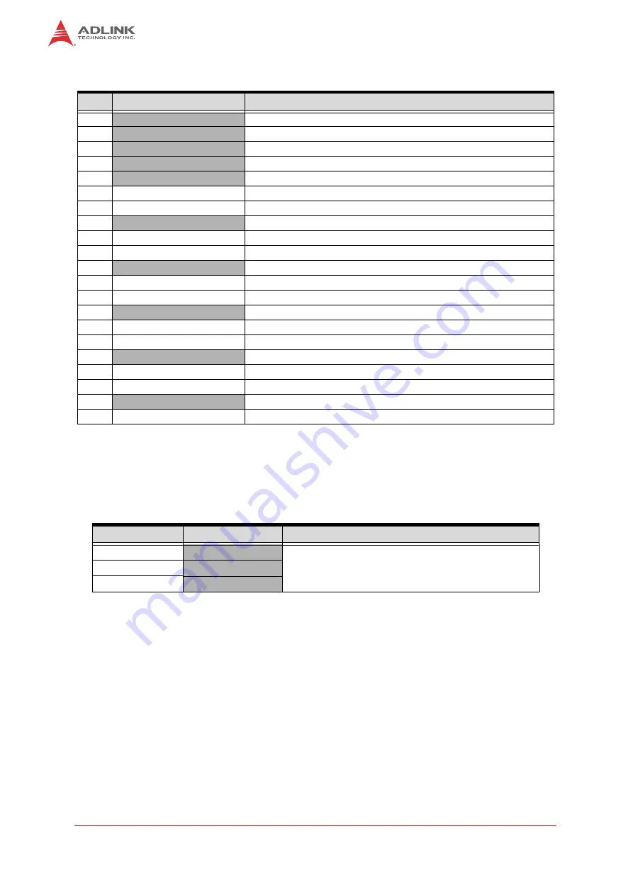
PS/2 Power Source Select (CN20)
Table 3-9 lists the pin signals of the PS/2 Power Source Select jumper header, which provides 3
pins in a single row with 0.079" (2.00mm) pitch.
NOTE: The shaded table cells denote power.
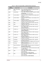
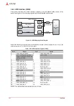
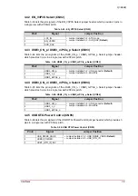
20
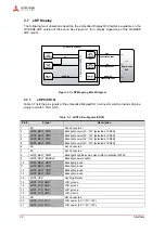
eDP1_LCD_VCC
LCD power (3.3V / 5V / 12V)
21
eDP1_LCD_VCC
LCD power (3.3V / 5V / 12V)
22
eDP1_LCD_VCC
LCD power (3.3V / 5V / 12V)
23
eDP1_LCD_VCC
LCD power (3.3V / 5V / 12V)
24
eDP1_HS_GND
High-Speed Ground
25
eDP1_AUX_n
Auxiliary differential pair - negative
26
eDP1_AUX_p
Auxiliary differential pair - positive
27
eDP1_HS_GND
High-Speed Ground
28
eDP1_TX0_p
Lane 0 Display Port primary channel differential pair 0 - positive
29
eDP1_TX0_n
Lane 0 Display Port primary channel differential pair 0 - negative
30
eDP1_HS_GND
High-Speed Ground
31
eDP1_TX1_p
Lane 1 Display Port primary channel differential pair 1 - positive
32
eDP1_TX1_n
Lane 1 Display Port primary channel differential pair 1 - negative
33
eDP1_HS_GND
High-Speed Ground
34
eDP1_TX2_p
Lane 2 Display Port primary channel differential pair 2 - positive
35
eDP1_TX2_n
Lane 2 Display Port primary channel differential pair 2 - negative
36
eDP1_HS_GND
High-Speed Ground
37
eDP1_TX3_p
Lane 3 Display Port primary channel differential pair 3 - positive
38
eDP1_TX3_n
Lane 3 Display Port primary channel differential pair 3 - negative
39
eD1_HS_GND
High-Speed Ground
40
NC
Not Connected
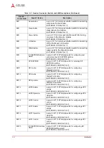
Table 3-9: PS/2 Power Source Select (CN20)
Pin #
Signal
Jumper Position
1
+V5P0_SBY
• Jumper Installed 1-2 - 5V Standby voltage (
Default
)
• Jumper Installed 2-3 - 5V A
2
+5V_PS2
3
+V5_IN
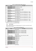
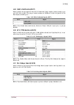
Table 3-8: eDP1 Video Signals (CN11) (Continued)
Pin #
Signal
Description