Interfaces
37
Q7-BASE
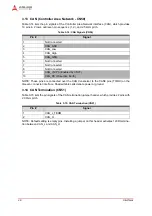
NOTE: The shaded table cells denote power or ground.
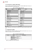
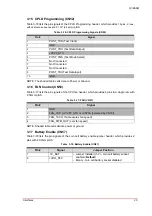
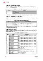
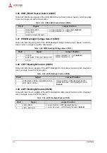
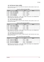
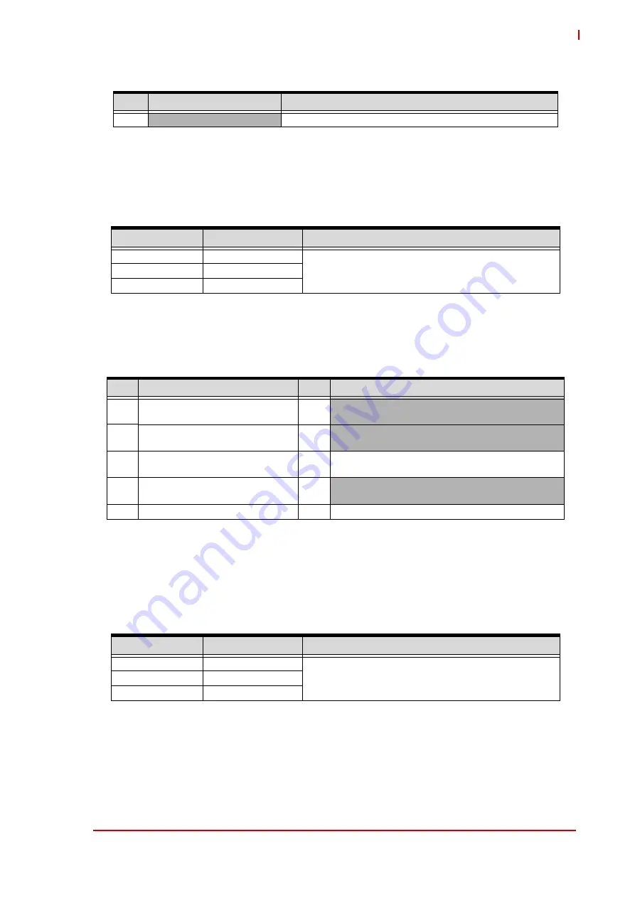
3.35 Display Mode Select (CN85)
Table 3-36 lists the pin signals of the Display Mode Select jumper header, which provides 3 pins
in a single row with 2.00mm pitch.
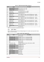
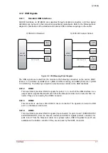
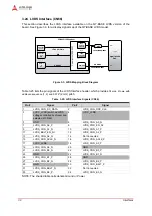
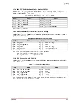
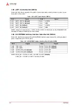
3.36 I2S (CN86)
Table 3-37 lists the pin signals of the I2S header, which provides 10 pins in two rows with
2.54mm pitch.
NOTE: Shaded table cells denote power or ground. The # symbol indicates the signal is Active
Low.
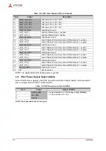
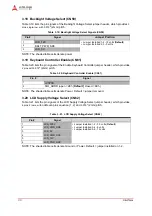
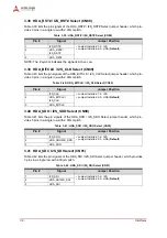
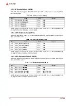
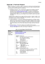
3.37 HDA_SYNC / I2S_WS Select (CN87)
Table 3-38 lists the pin signals of the HDA_SYNC / I2S_WS Select jumper header, which pro-
vides 3 pins in a single row with 2.00mm pitch.
20
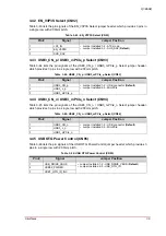
+3V3S_DP
DisplayPort Power
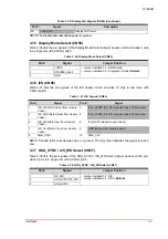
Table 3-36: Display Mode Select (CN85)
Pin #
Signal
Jumper Position
1
+V3PS
• Jumper Installed 1-2 - HDMI mode
• Jumper Installed 2-3 - DisplayPort mode (
Default
)
2
DP/HDMI_SEL2
3
GND
Table 3-37: I2S Signals (CN86)
Pin #
Signal
Pin #
Signal
1
I2S_WS (Word Select from module
Codec)
2
I2S_+V3P3S (3.3V for module Codec, 250mA max)
3
I2S_SDO (Data Output from module
Codec)
4
I2S_+V1P8S (1.8V for module Codec, 250mA max)
5
I2S_SDI (Data Input from module
Codec)
6
I2S_RST# (Reset module Codec)
7
I2S_CLK (Data Clock from module
Codec)
8
GND (Ground for module Codec)
9
SMB_DATA
10
SMB_CLK
Table 3-38: HDA_SYNC / I2S_WS Select (CN87)
Pin #
Signal
Jumper Position
1
I2S_WS
• Jumper Installed 1-2 - I2S
• Jumper Installed 2-3 - HDA (
Default
)
2
HDA_SYNC/I2S_WS
3
HDA_SYNC
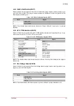
Table 3-35: DisplayPort Signals (CN84) (Continued)
Pin #
Signal
Description