26
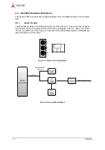
Interfaces
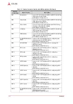
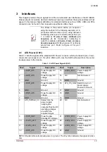
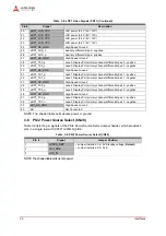
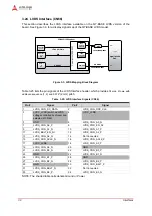
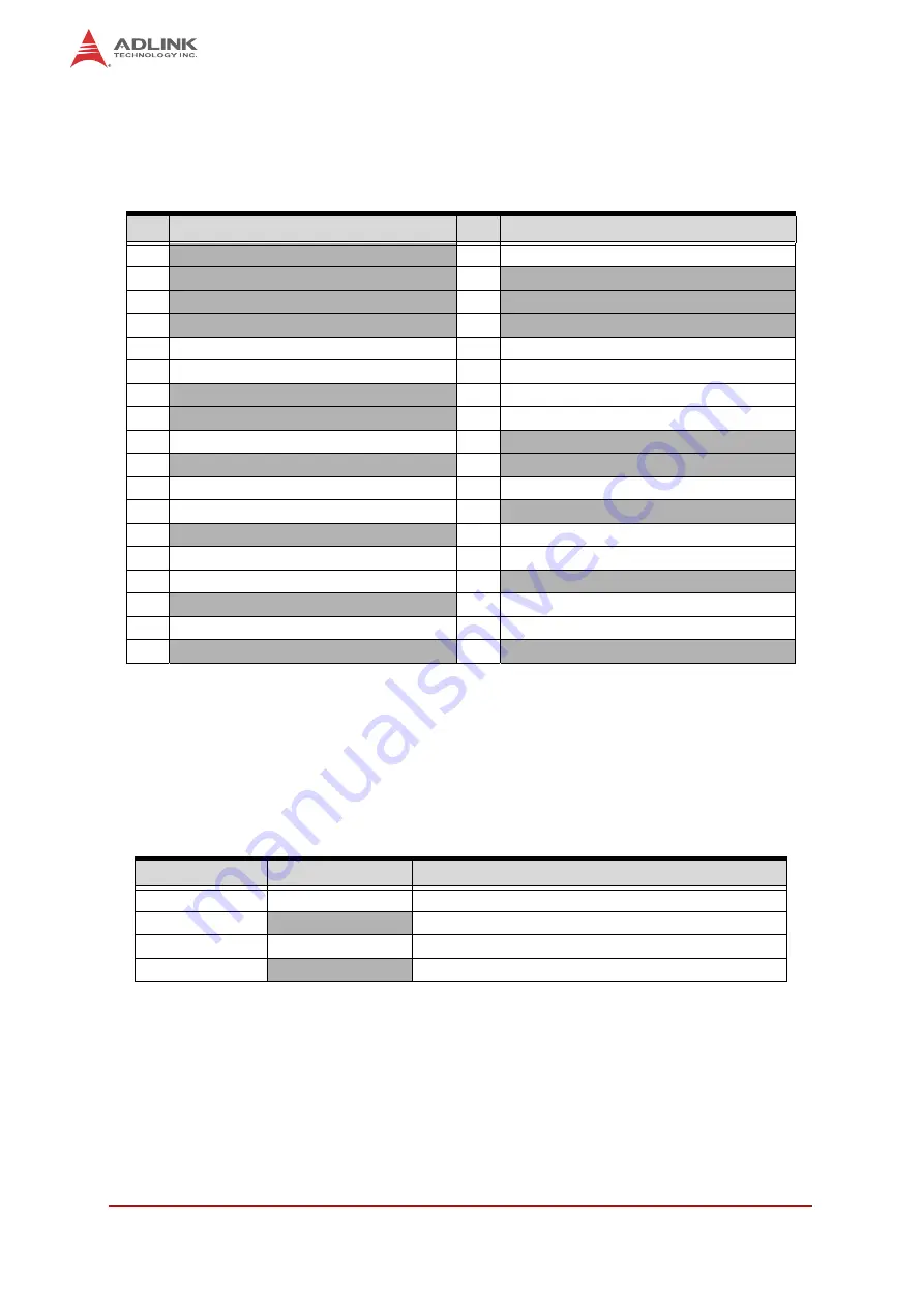
3.10 PCI Express x1 (CN42, CN44, CN45)
Table 3-12 lists the signals for the PCIe A x1 connector, which provides 36 pins, two rows, con-
secutive pin sequence (1, 13) with 1.00mm pitch.
NOTE: Shaded table cells denote power or ground. The # symbol indicates the signal is Active
Low.
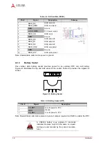
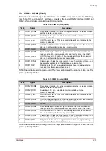
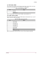
3.11 Digital Audio (CN46)
Table 3-13 lists the pin signals of the Digital Audio interface, which provides
4 pins, 2 rows, with
odd/even pin sequence (1, 2) and
0.079
" (2mm) pitch.
NOTE: The shaded table cells denote ground.
Table 3-12: PCIe x1 (CN42, CN44, CN45)
Pin
Signal
Pin
Signal
B1
+V12P0_ATX
A1
PCIE_A_PRSNT1#
B2
+V12P0_ATX
A2
+V12P0_ATX
B3
+V12P0_ATX
A3
+V12P0_ATX
B4
GND
A4
GND
B5
SMB_CK
A5
Not Connected
B6
SMB_DAT
A6
Not Connected
B7
GND
A7
Not Connected
B8
+3VP3
A8
Not Connected
B9
Not Connected
A9
+3VP3S
B10
+3VP3A (auxiliary)
A10
+3VP3S
B11
PCIE_WAKE# A11
PCIE_RST#
B12
Not Connected
A12
GND
B13
GND
A13
PCIE_CLK_P
B14
PCIE_TX_P
A14
PCIE_CLK_N
B15
PCIE_TX_N
A15
GND
B16
GND
A16
PCIE_RX_P
B17
PCIE_PRSNT2#
A17
PCIE_RX_N
B18
GND
A18
GND
Table 3-13: Digital Audio Signals (CN46)
Pin #
Signal
Description
1
CON_SPDIFI
Digital Audio In
2
GND
Ground
3
CON_SPDIFO
Digital Audio Out
4
GND
Ground