
Interfaces
23
Q7-BASE
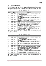
NOTE: The shaded table cells denote power or ground.
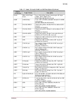
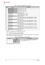
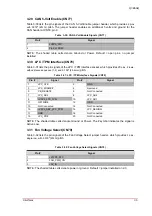
3.7.2
eDP1 (CN11)
Table 3-8 lists the pin signals of the embedded DisplayPort 1 connector, which provides 40-pins,
single row with 0.5mm pitch.
22
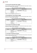
eDP0_LCD_VCC
LCD power (3.3V / 5V / 12V)
23
eDP0_LCD_VCC
LCD power (3.3V / 5V / 12V)
24
eDP0_HS_GND
High-Speed Ground
25
eDP0_AUX_n
Auxiliary differential pair - negative
26
eDP0_AUX_p
Auxiliary differential pair - positive
27
eDP0_HS_GND
High-Speed Ground
28
eDP0_TX0_p
Lane 0 Display Port primary channel differential pair 0 - positive
29
eDP0_TX0_n
Lane 0 Display Port primary channel differential pair 0 - negative
30
eDP0_HS_GND
High-Speed Ground
31
eDP0_TX1_p
Lane 1 Display Port primary channel differential pair 1 - positive
32
eDP0_TX1_n
Lane 1 Display Port primary channel differential pair 1 - negative
33
eDP0_HS_GND
High-Speed Ground
34
eDP0_TX2_p
Lane 2 Display Port primary channel differential pair 2 - positive
35
eDP0_TX2_n
Lane 2 Display Port primary channel differential pair 2 - negative
36
eDP0_HS_GND
High-Speed Ground
37
eDP0_TX3_p
Lane 3 Display Port primary channel differential pair 3 - positive
38
eDP0_TX3_n
Lane 3 Display Port primary channel differential pair 3 - negative
39
eDP0_HS_GND
High-Speed Ground
40
NC
Not Connected
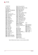
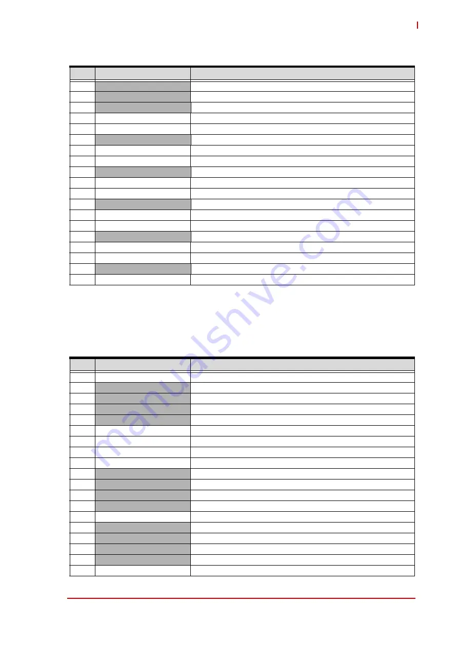
Table 3-8: eDP1 Video Signals (CN11)
Pin #
Signal
Description
1
NC
Not Connected
2
eDP1_BKLT_PWR
Backlight power (5V / 12V [selected at CN59])
3
eDP1_BKLT_PWR
Backlight power (5V / 12V [selected at CN59])
4
eDP1_BKLT_PWR
Backlight power (5V / 12V [selected at CN59])
5
eDP1_BKLT_PWR
Backlight power (5V / 12V [selected at CN59])
6
NC
Not Connected
7
NC
Not Connected
8
eDP1_BKLT_PWM
Backlight brightness via pulse width modulation (PWM)
9
eDP1_BKLT_ENABLE
Backlight power enable
10
eDP1_BKLT_GND
Backlight ground
11
eDP1_BKLT_GND
Backlight ground
12
eDP1_BKLT_GND
Backlight ground
13
eDP1_BKLT_GND
Backlight ground
14
eDP1_HPD
Hot Plug Detect
15
eDP1_LCD_GND
LCD ground
16
eDP1_LCD_GND
LCD ground
17
eDP1_LCD_GND
LCD ground
18
eDP1_LCD_GND
LCD ground
19
NC
Not Connected
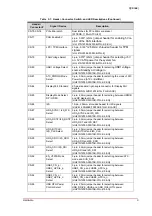
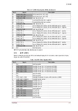
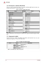
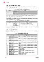
Table 3-7: eDP0 Video Signals (CN10) (Continued)
Pin #
Signal
Description


