Motion Creator
161
Z
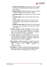
In Manual Pulser Move
, this causes the axis to go into
pulse move. The speed limit is the value set by Maxi-
mum Velocity.
Z
Right play button
: Click this button to let the card start
to outlet pulses according to previous setting.
Z
In Absolute Mode
, this causes the axis to move to posi-
tion.
Z
In Relative Mode
, this causes the axis to move back-
wards.
Z
In Cont. Move
, this causes the axis to start to move
according to the velocity setting, but in the opposite
direction.
Z
In Manual Pulser Move
, this causes the axis to go into
pulse move. The speed limit is the value set by Maxi-
mum Velocity.
16.
Change Position On The Fly Button
: When enabled,
you can change the target position of the current
motion. The new position must be defined in Position2.
The related function is
_8164_p_change()
.
17.
Change Velocity On The Fly Button
: When enabled,
you can change the velocity of the current motion. The
new velocity must be defined in Maximum Velocity. The
related function is
_8164_v_change()
18.
Stop Button
: Clicking this button causes the card to
decelerate and stop. The deceleration time is defined in
Decel. Time. The related function is
_8164_sd_stop()
.
19.
I/O Status
: The status of motion I/O. Light-On means the
motion I/O is active while Light-Off indicates inactivity.
The related function is
_8164_get_io_status()
.
Summary of Contents for MPC-8164
Page 4: ......
Page 12: ......
Page 14: ...2 Introduction Figure 1 1 PCI 8164 block diagram ...
Page 50: ...38 Installation ...
Page 70: ...58 Signal Connections ...
Page 74: ...62 Signal Connections 3 17 1 Isolated input channels 3 17 2 Isolated output channels ...
Page 75: ...Signal Connections 63 3 17 3 Example of input connection ...
Page 76: ...64 Signal Connections 3 17 4 Example of output connections ...
Page 109: ...Operation Theory 97 ...
Page 110: ...98 Operation Theory ...
Page 111: ...Operation Theory 99 ...
Page 112: ...100 Operation Theory ...
Page 113: ...Operation Theory 101 ...
Page 148: ...136 Operation Theory Users can use this function to check if auto trigger is running Results ...
Page 280: ...268 Connection Example Figure 7 2 Connection of PCI 8164 with Panasonic Driver ...
Page 287: ...Connection Example 275 7 3 3 Mechanical Dimensions ...
Page 297: ...Connection Example 285 7 5 2 Mechanical Dimensions ...
Page 300: ...288 Connection Example 7 6 Wiring with DIN 814M J3A ...
Page 304: ...292 Connection Example 7 7 Wiring with DIN 814Y ...
Page 308: ...296 ...

