22
Installation
2.6 MPC-8164 hardware installation
2.6.1 Hardware configuration
The MPC-8164 card is PC104-compliant. The onboard DIP
switches and jumpers assign the card’s I/O port locations and IRQ
channels.
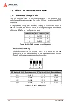
A single-board setup has a default setting of 0x200 and IRQ5. In
GEME systems, the default value varies depending on the location
of the card. Refer to the following table:
Table 2-1: GEME hardware configuration
Base address setting
The base address is set by SW1 (pins 2 to 4). Note that pin 1 is
reserved. If all DIPs are set to OFF, the base address is 0x200.
Default settings are dependent on the order.
Table 2-2: Base Addresses
GEME level Base address IRQ
1
0x300
9
2
0x200
5
3
0x280
10
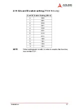
DIP Switch (2 3 4) Base Address DIP Switch (2 3 4) Base Address
1 1 1
0x3C0
1 1 0
0x2C0
0 1 1
0x380
0 1 0
0x280
1 0 1
0x340
1 0 0
0x240
0 0 1
0x300
0 0 0
0x200
Summary of Contents for MPC-8164
Page 4: ......
Page 12: ......
Page 14: ...2 Introduction Figure 1 1 PCI 8164 block diagram ...
Page 50: ...38 Installation ...
Page 70: ...58 Signal Connections ...
Page 74: ...62 Signal Connections 3 17 1 Isolated input channels 3 17 2 Isolated output channels ...
Page 75: ...Signal Connections 63 3 17 3 Example of input connection ...
Page 76: ...64 Signal Connections 3 17 4 Example of output connections ...
Page 109: ...Operation Theory 97 ...
Page 110: ...98 Operation Theory ...
Page 111: ...Operation Theory 99 ...
Page 112: ...100 Operation Theory ...
Page 113: ...Operation Theory 101 ...
Page 148: ...136 Operation Theory Users can use this function to check if auto trigger is running Results ...
Page 280: ...268 Connection Example Figure 7 2 Connection of PCI 8164 with Panasonic Driver ...
Page 287: ...Connection Example 275 7 3 3 Mechanical Dimensions ...
Page 297: ...Connection Example 285 7 5 2 Mechanical Dimensions ...
Page 300: ...288 Connection Example 7 6 Wiring with DIN 814M J3A ...
Page 304: ...292 Connection Example 7 7 Wiring with DIN 814Y ...
Page 308: ...296 ...


