262
Function Library
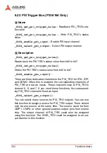
6.22 PXI Trigger Bus (PXI-8164 Only)
@ Name
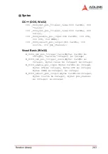
_8164_get_pxi_trigger_value
– Readback PXI_TRG’s sta-
tus value
_8164_set_pxi_trigger_value
– Write PXI_TRG’s status
value
_8164_enable_pxi_input
– Enable PXI input channel
_8164_select_pxi_output
– Select PXI output channel
@ Description
_8164_get_pxi_trigger_value()
:
Reads back the PXI TRG’s status value from bit0 to bit7.
_8164_set_pxi_trigger_value()
:
Writes the PXI TRG’s status value from bit0 to bit7.
_8164_enable_pxi_input()
:
There are three dedicated channels in the PXI_TRG for STA, STP,
and CEMG. When this is enabled, the corresponding channels of
PXI_TRG are set as inputs. These channels map to PXI_TRG’s
channel 5, 6, and 7. If you need these functions, the correspond-
ing PXI_TRG channel is fixed as Input.
_8164_select_pxi_output()
:
You can select many sources for PXI_TRG outputs. You can use
this function to assign a source for PXI_TRG output. There should
only be one source at the same time. The source could be from
CMP1, CMP2, or other general purpose output pins from motion
chip. The output channel of PXI_TRG could also be assigned
using this function. The STAR_TRG could be assigned to an out-
put channel in this function.
Summary of Contents for MPC-8164
Page 4: ......
Page 12: ......
Page 14: ...2 Introduction Figure 1 1 PCI 8164 block diagram ...
Page 50: ...38 Installation ...
Page 70: ...58 Signal Connections ...
Page 74: ...62 Signal Connections 3 17 1 Isolated input channels 3 17 2 Isolated output channels ...
Page 75: ...Signal Connections 63 3 17 3 Example of input connection ...
Page 76: ...64 Signal Connections 3 17 4 Example of output connections ...
Page 109: ...Operation Theory 97 ...
Page 110: ...98 Operation Theory ...
Page 111: ...Operation Theory 99 ...
Page 112: ...100 Operation Theory ...
Page 113: ...Operation Theory 101 ...
Page 148: ...136 Operation Theory Users can use this function to check if auto trigger is running Results ...
Page 280: ...268 Connection Example Figure 7 2 Connection of PCI 8164 with Panasonic Driver ...
Page 287: ...Connection Example 275 7 3 3 Mechanical Dimensions ...
Page 297: ...Connection Example 285 7 5 2 Mechanical Dimensions ...
Page 300: ...288 Connection Example 7 6 Wiring with DIN 814M J3A ...
Page 304: ...292 Connection Example 7 7 Wiring with DIN 814Y ...
Page 308: ...296 ...


