Operation Theory
147
4.11 PXI Trigger Bus (PXI-8164 only)
There are eight general trigger channels in PXI bus. They are
called PXI_TRG[0] to PXI_TRG[7]. All channels can be pro-
grammed as input or output. These trigger channels are for inter-
board control synchronization.
For example, if there are two PXI cards, card A and card B in one
system, Card A will send a trigger signal through PXI_TRG to card
B and card B is waiting for this signal to do some action. There is
another dedicated channel for trigger input and output, They are
called PXI_STAR(input) and STAR_TRG(output). They can not be
programmed as input or ouput individually. They can only be
enabled or disabled.
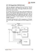
This section describes the PXI_TRG’s arrangement in PXI-8164
and how it is used. The following figure is the block diagram of PXI
bus.
Summary of Contents for MPC-8164
Page 4: ......
Page 12: ......
Page 14: ...2 Introduction Figure 1 1 PCI 8164 block diagram ...
Page 50: ...38 Installation ...
Page 70: ...58 Signal Connections ...
Page 74: ...62 Signal Connections 3 17 1 Isolated input channels 3 17 2 Isolated output channels ...
Page 75: ...Signal Connections 63 3 17 3 Example of input connection ...
Page 76: ...64 Signal Connections 3 17 4 Example of output connections ...
Page 109: ...Operation Theory 97 ...
Page 110: ...98 Operation Theory ...
Page 111: ...Operation Theory 99 ...
Page 112: ...100 Operation Theory ...
Page 113: ...Operation Theory 101 ...
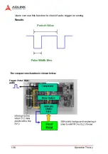
Page 148: ...136 Operation Theory Users can use this function to check if auto trigger is running Results ...
Page 280: ...268 Connection Example Figure 7 2 Connection of PCI 8164 with Panasonic Driver ...
Page 287: ...Connection Example 275 7 3 3 Mechanical Dimensions ...
Page 297: ...Connection Example 285 7 5 2 Mechanical Dimensions ...
Page 300: ...288 Connection Example 7 6 Wiring with DIN 814M J3A ...
Page 304: ...292 Connection Example 7 7 Wiring with DIN 814Y ...
Page 308: ...296 ...


