53
ActronAir
is constantly seeking ways to improve the design of it’s products, therefore specifications are subject to change without notice.
Copyright © 2017 Actron Engineering Pty. Ltd.
VARIOUS ROOM TEMPERATURE SENSOR CONNECTIONS
Instructions describe below are applicable to Tri-Capacity models
with controller software Version 2021-136-2003 and onwards.
IMPORTANT NOTE
The new Tri-Capacity controller software gives the user various options to connect the Room Temperature Sensor
(2060-036 or LM-RS) from one of three available inputs. These options eliminate the unnecessary connection of the
Room Temperature Sensor to the OUTDOOR or INDOOR board.
As an example, the Room Temperature Sensor is connected to the INDOOR board which will need to mask alarms
associated with Room Temperature Sensor input to main CM100 controller. There is now an option to disable the alarms
associated with this input.
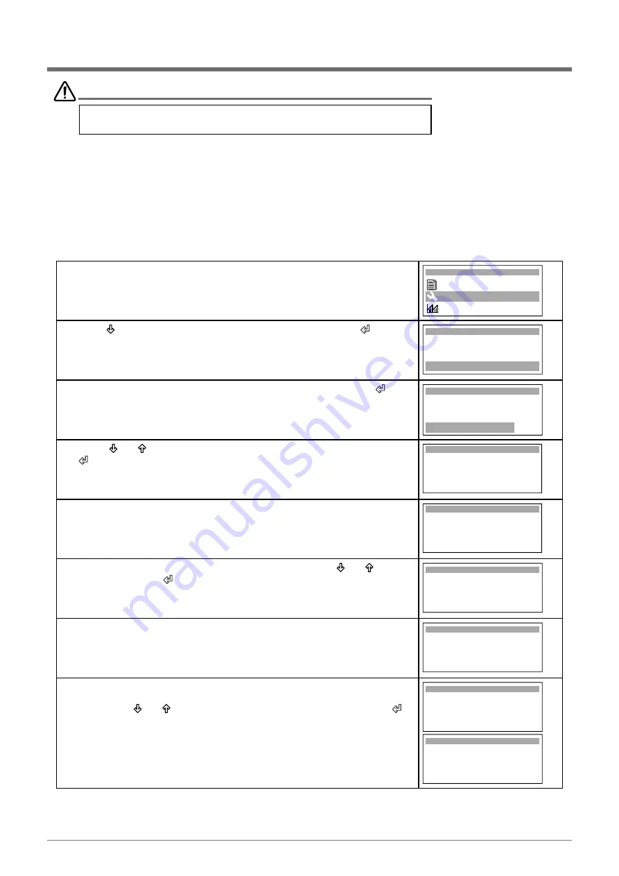
Shown below are the procedure and CP05 / CP10 display progressions which will guide the user to enable or disable
the alarms associated with various Room Temperature Sensor connection input options.
1. Enter
G. Service
menu.
G. Service
F. Data logger
Main Menu G
H. Manufacturer
2. Press
“ ”
Button to scroll down into “
Gf. Service settings
” then
“ ”
.
NOTE
: Service Password is “
7378
”.
Service menu Gf
d. Working hours
f. Service settings
e. Communicate config.
3. Scroll down to “
Gfc. Thermoregulation
” screen and then press the
“ ”
to
enter the menu.
a. Working hour set
b . Probe adjustment
c . Thermoregulation
Service Menu Gfc
4. Using
“ ”
or
“ ”
Button, select
“Thermoregulation Gfc2”
and then press
“ ”
Button to select
“OUTDOOR”
or
“INDOOR”
temperature sensor,
depending on where about the
Room Temperature Sensor
is connected.
Room Temperature
After Hours SW & Temp
Wall Cont Temp : 25.4
O
C
use OUTDOOR sensor
Room Temp : 13.8
O
C
Probe weight Value : 0
Control Value : 13.8
O
C
Thermoregulation Gfc2
5. If the OUTDOOR controller (CM100) is used with Control Interface (CL01),
then this will allow the user to use the Control Interface (built-in ) temp sensor
by changing the “Probe weight Value” to 100 as shown in the screen.
Room Temperature
After Hours SW & Temp
Wall Cont Temp : 25.4
O
C
use OUTDOOR sensor
Room Temp : 13.8
O
C
Probe weight Value : 100
Control Value : 13.8
O
C
Thermoregulation Gfc2
6. Scroll down into
“Alarm disable Gfc17”
screen using the “ ”
or
“ ”
Button
and then press the
“ ”
Button to enter
Alarm disable Gfc17
RTN AIR Sensor : No
Outdoor Unit
7. Disable the alarm associated with the Outdoor Controller input by changing
“RTN AIR Sensor”
to
“Yes”
. This will mask any alarm when the Room
Temp. Sensor is not connected to the Outdoor Controller input, as the user
has chosen to use the CL01 Control Interface built-in temperature sensor.
Alarm disable Gfc17
RTN AIR Sensor : Yes
Outdoor Unit
8. On the other hand, disable the alarm associated with the Indoor Controller
input via
“Alarm disable Gfc18”
screen.
Use the the “ ”
or
“ ”
Button to get into this screen and then press the
“ ”
Button to lock it in.
Mask any alarm
when the Room Temperature Sensor is not connected to the Outdoor
Controller input by changing
“RTN AIR
Sensor”
to
“Yes”
.
NOTE:
Gfc18 screen is available on split models only.
Alarm disable Gfc18
RTN AIR Sensor : No
Indoor Unit
Alarm disable Gfc18
RTN AIR Sensor : Yes
Indoor Unit
NOTE:
The INDOOR / OUTDOOR Room Temperature Sensor connection options are available on CAY units only. For
PKY units, the user has the option to disable the alarm from the OUTDOOR Room Temp. Sensor connection via
Service Menu
“Alarm disable Gfc17”
screen.


