IP482 Industrial I/O Pack User’s Manual Counter Timer Module
__________________________________________________________________
_________________________________________________________________________________________
Acromag, Inc. Tel:248-295-0310 Fax:248-624-9234 Email:[email protected] http://www.acromag.com
32
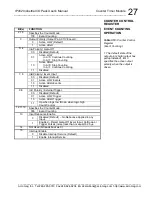
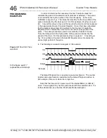
Input Period Measurement
The counter/timer may be used to measure the period of an input signal
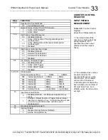
at the counter input InA. Setting bits 2 to 0 of the Counter Control Register
to logic “110” configures the counter for period measurement. The first input
cycle after period measurement is triggered will be measured.
InA is used to input the signal to be measured. Period measurement can
be initiated on the active low or high portion of the waveform. The period of
signal is the time the signal is low added to the time the signal is high,
before it repeats.
InB can be used to input an external clock for period measurement. Bits
7 and 6 must be set to either logic “01” or “10”. Additionally, the clock
source bits 12, 11, and 10 must be set to logic “101” to enable external clock
input. Period measurement can alternatively be internally clocked using
control register bits 12, 11, and 10. Available frequencies vary depending
on carrier operational frequency.
InC can be used to externally trigger period measurement. Additionally,
Period Measurement can be triggered internally via the Counter Trigger
Register at the base a offset 04H. An initial trigger, software or
external, starts period measurement at the beginning of the next active
period.
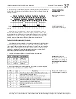
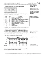
The period being measured serves as an enable control for an up-
counter whose value can be read from the Counter Read Back Register.
When triggered the counter is reset. Then, the active polarity of InA starts
period measurement. The counter increments by one for each clock pulse
during the input signal period (InA). The resultant period is equivalent to the
count value read from the Counter Read Back Register, multiplied by the
clock period. A 1.75
s output pulse will be generated at the counter output
pin to signal the completion of a given measurement. Note that the
measured period may be in error by
1 clock cycle.
Reading a counter value of 0xFFFF hex indicates that the pulse duration
is longer than the current counter size and clock frequency can measure.
Upon reading of this overflow value you must select a slower frequency and
re-measure.
An interrupt can be generated upon completion of a given period
measurement, if enabled via the interrupt enable bit of the Counter Control
Register (bit 15). The interrupt will be generated upon completion of the first
complete waveform cycle after the counter is triggered. The interrupt will
occur even if an external clock is selected but no clock signal is provided on
InB. The count value will be zero in this case. The interrupt, once driven
active, will remain pending until released by setting the required bit of the
Interrupt Status/Clear
register at the base a offset 02H. A pending
interrupt can also be cleared, by setting Counter Control register bit-15 to
logic low.
COUNTER CONTROL
REGISTER

