IP482 Industrial I/O Pack User’s Manual Counter Timer Module
__________________________________________________________________
_________________________________________________________________________________________
Acromag, Inc. Tel:248-295-0310 Fax:248-624-9234 Email:[email protected] http://www.acromag.com
2
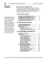
IMPORTANT SAFETY CONSIDERATIONS
You must consider the possible negative effects of power, wiring,
component, sensor, or software failure in the design of any type of
control or monitoring system. This is very important where property
loss or human life is involved. It is important that you perform
satisfactory overall system design and it is agreed between you and
Acromag, that this is your responsibility.
1.0 General Information
KEY IP482 COUNTER/TI
MER FEATURES.........…...
4
INDUSTRIAL I/O PACK INTERFACE FEATURES...
5
SIGNAL INTERFACE PRODUCTS……………………
5
IP MODULE ActiveX CONTROL SOFTWARE..........
6
IP MODULE Win32 CONTROL SOFTWARE….........
6
IP MODULE VxWORKS SOFTWARE
.....…...…….….
7
2.0 PREPARATION FOR USE
UNPACKING AND INSPECTION...…………………...
7
CARD CAGE CONSIDERATIONS.........……………..
7
BOARD CONFIGURATION..........................………...
7
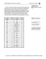
CONNECTORS........…………………………………….
8
IP Field I/O Connector (P2)…...………………...
8
IP Logic Interface Connector (P1)..…….……...
9
I/O Noise and Grounding Considerations.......
10
3.0 PROGRAMMING INFORMATION
IP IDENTIFICATION SPACE.....…….…………………
11
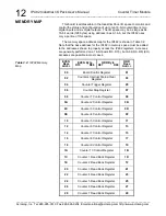
MEMORY MAP..............................................………...
12
Board Control Register.....................................
14
Interrupt Status/Clear Register........…………..
14
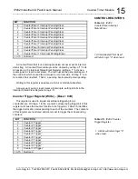
Counter Trigger Register..................................
15
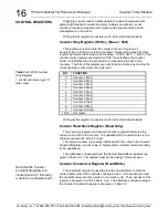
Counter Stop Register...……………….………..
16
Counter Read Back Register....………………...
16
Counter Constant A Register.……………….....
16
Counter Constant B Register............................
17
Digital Input Register…………………………….
17
Digital Output Register…………………………..
17
Interrupt Vector Register………………………..
18
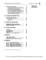
COUNTER CONTROL REGISTER.............................
18
Quadrature Position Measurement…...............
19
Pulse Width Modulation......……...……...……...
22
Watchdog Timer Operation.……………...……..
24
Event Counting Operation..........................…...
26
Frequency Measurement Operation.................
28
Input Pulse Width Measurement……………….
30
Input Period Measurement.……………………..
32
One-
Shot Pulse Mode.........……………………..
34
TABLE OF
CONTENTS
The information of this manual
may change without notice.
Acromag makes no warranty
of any kind with regard to this
material, including, but not
limited to, the implied
warranties of merchantability
and fitness for a particular
purpose. Further, Acromag
assumes no responsibility for
any errors that may appear in
this manual and makes no
commitment to update, or
keep current, the information
contained in this manual. No
part of this manual may be
copied or reproduced in any
form without the prior written
consent of Acromag, Inc.

