IP482 Industrial I/O Pack User’s Manual Counter Timer Module
__________________________________________________________________
_________________________________________________________________________________________
Acromag, Inc. Tel:248-295-0310 Fax:248-624-9234 Email:[email protected] http://www.acromag.com
18
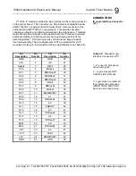
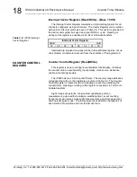
Interrupt Vector Register (Read/Write) - (Base + 5CH)
The Interrupt Vector Register maintains an 8-bit interrupt pointer for all
channels configured as input channels. The Vector Register can be written
with an 8-bit interrupt vector as seen in Table 3.9. This vector is provided to
the carrier and system bus upon an active INTSEL
cycle. Reading or
writing to this register is possible via 16-bit or 8-bit data transfers.
Interrupt Vector Register
MSB
LSB
07
06
05
04
03
02
01
00
Interrupts are released on access to the Interrupt Status register. Issue
of a software or hardware reset will clear the contents of this register to 0.
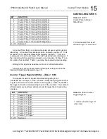
Counter Control Register (Read/Write)
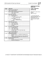
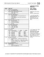
This register is used to configure counter/timer functionality. It defines
the counter mode, output polarity, input polarity, clock source, debounce
enable, and interrupt enable.
The IP482 has ten 16-bit Counter/Timers. The memory map addresses
corresponding to the control registers are given in Table 3.2. The Counter
Control Register is cleared (set to 0) following a reset, thus disabling the
counter/timer. Reading or writing to this register is possible via 16-bit or 8-
bit data transfers.
Eight modes of operation are provided: quadrature position
measurement, pulse width modulation, watchdog timer, event counting,
frequency measurement, pulse width measurement, period measurement,
and one-shot pulse mode. The following sections describe the features of
each method of operation and how to best use them.
Table 3.9:
IP482 Interrupt
Vector Register
COUNTER CONTROL
REGISTER


