IP482 Industrial I/O Pack User’s Manual Counter Timer Module
___________________________________________________________________
________________________________________________________________________________________
Acromag, Inc. Tel:248-295-0310 Fax:248-624-9234 Email:[email protected] http://www.acromag.com
19
Quadrature Position Measurement
The counter/timers may be used to perform position measurements from
quadrature motion encoders. Bits 2 to 0 of the Counter Control Register set
to logic ”001” configure the counter for quadrature measurement.
A quadrature encoder can have up to three channels: A, B, and Index.
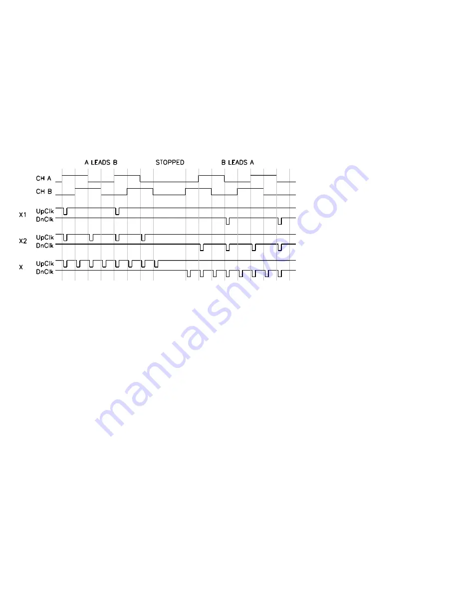
When channel A leads channel B by 90
in a quadrature cycle, the counter
increments. When channel B leads channel A by 90
in a quadrature cycle,
the counter decrements. The number of increments or decrements per
cycle depends on the type of encoding: X1, X2, or X4.
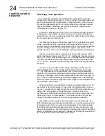
An X1 encoding Increment occurs on the rising edge of channel A when
channel A leads channel B. An X1 encoding decrement occurs on the
falling edge of channel A when channel B leads channel A.
For X2 encoding, two increments or decrements (on each edge of
channel A) result from each cycle. The counter increments when A leads B
and decrements when B leads A.
For X4 encoding, four increments or decrements (on each edge of
channel A and B) result from each cycle. The counter increments when A
leads B and decrements when B leads A.
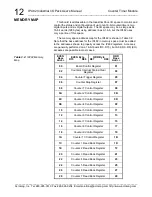
Quadrature measurement must be triggered internally via the Counter
Trigger Register at the base a offset 04H. An initial software trigger
starts quadrature position measurement operation.
InA and InB input signals are used to input the channel A and channel B
input signals, respectively. The counter will increment when channel A
leads channel B and will decrement when channel B leads channel A.
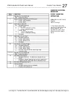
Three rates of increments and decrements are available X1, X2, and X4
which are programmed via counter timer control register bits 5 and 4.
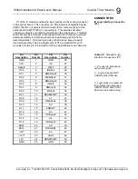
Channel B is enabled for input by setting bit-
6 to a logic “1”.
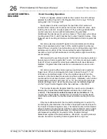
InC can be used for the Index signal. Encoders that have an index
channel can cause the counter to reload with the Counter Constant B value
in a specified phase of the quadrature cycle. Reload can be programmed to
occur in any one of the four phases in a quadrature cycle. You must ensure
that the Index channel is high during at least a portion of the phase you
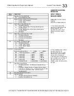
specify for reload. The phase can be selected via the counter timer control
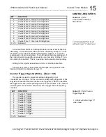
register bits 9, 8, and 7 as seen in Table 3.10.
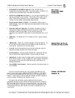
COUNTER CONTROL
REGISTER
Figure 3.1
: Shows a
quadrature cycle and the
resulting increments and
decrements for X1, X2, and
X4 encoding.
4

