IP482 Industrial I/O Pack User’s Manual Counter Timer Module
___________________________________________________________________
________________________________________________________________________________________
Acromag, Inc. Tel:248-295-0310 Fax:248-624-9234 Email:[email protected] http://www.acromag.com
43
2. Write the following information, 959DH, to Counter 9 Control Register
located at base address plus an offset of 18H.
Bits
Logic
Operation
2,1,0
101
Sets the counter to Pulse-Width Measurement.
3
1
Sets the output to active high.
5,4
01
Sets the Pulse input (InA) to active low.
7,6
10
Enables the external clock input (InB).
9,8
01
Enables the external Trigger Input (InC) to active low.
12,11,10
101
Sets the clock to an external source.
13
0
Disables input debounce on InA and InC.
14
0
Not used.
15
1
Enables interrupts.
3. Do
not
write to either of the Counter 9 Constant Registers. They are not
required for pulse-width measurement and writing to them can cause errors.
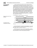
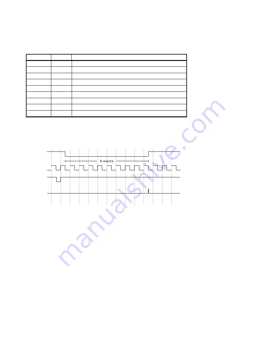
4. The following is a waveform diagram of this example.
i
Output
InB
InC
InA
Interrupts
The length of the low portion of the InA pulse is calculated by multiplying
the number in the Counter 9 Read Back Register, located at base address
plus an offset of 2CH, by the period of the selected clock. Note that the
value in the Read Back Register is stored in Hex and requires conversion to
decimal for calculations. In this case the value in the Read Back Register is
9, since there were nine high pulses during the active InA signal. The
period of the clock is calculated by taking the inverse of the frequency of the
clock. For this example, the frequency was 100KHz. Therefore the clock
period is 1/100KHz, which is equal to 10
s. The clock period multiplied by
the Read Back Register 10
s x 9, is equal to 90
s, the duration of the active
low InA pulse. This value may be in error by
1 clock period.
Note that the InA and InC inputs run off the internal 8MHz (or 32MHz)
clock. Those signals may not be synchronous with the selected clock. The
output pulse is active for 1.75
s. If debounce was enabled, the output pulse
will occur 2.5
s after the completion of the input pulse. Additionally, the
counter must be re-triggered before any further measurements take place.
For more information, see the Pulse-Width Measurement description.
PROGRAMMING
EXAMPLES
Table 3.29:
Pulse-Width
Measurement Control Register
9 Settings
Figure 3.7:
Pulse-Width
Measurement waveform
In the figure each “i”
represents an interrupt


