


IP482 Industrial I/O Pack User’s Manual Counter Timer Module
__________________________________________________________________
_________________________________________________________________________________________
Acromag, Inc. Tel:248-295-0310 Fax:248-624-9234 Email:[email protected] http://www.acromag.com
16
Triggering may be used to initiate quadrature position measurement,
pulse width modulation, watchdog timer (initiates countdown), event
counting, frequency measurement, pulse-width measurement, period
measurement, or one-shot.
Writing to this register is possible via 16-bit or 8-bit data transfers.
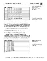
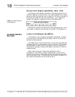
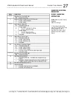
Counter Stop Register (Write) - (Base + 06H)
This register is used to stop the counters of one or a group of
Counter/Timers. Writing a 1 to the counter’s corresponding stop bit of this
register will cause the counter to be disabled. That is, bits 2, 1, and 0 of the
counter
control register are cleared to “000” thus disabling the counter.
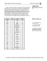
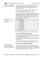
Table 3.6 identifies the stop bit location corresponding to each of the
counters. The bits of this register are not stored and merely act to stop the
corresponding counter when set logic high.
BIT
FUNCTION
0
Counter 1 Stop
1
1
Counter 2 Stop
1
2
Counter 3 Stop
1
3
Counter 4 Stop
1
4
Counter 5 Stop
1
5
Counter 6 Stop
1
6
Counter 7 Stop
1
7
Counter 8 Stop
1
8
Counter 9 Stop
1
9
Counter 10 Stop
1
10-15
Not Used
1
Writing to this register is possible via 16-bit or 8-bit data transfers.
Counter Read Back Register (Read Only)
This read-only register is a dynamic function register that returns the
current value held in the counter. It is updated with the value stored in the
internal counter each time it is read.
The internal counter is generally initialized with the value in the Counter
Constant Register, and its value is incremented or decremented according
to the application.
The addresses corresponding to the Counter Read Back registers are
given in Table 3.2. This register must be read using 16-bit accesses.
Counter Constant A Register (Read/Write)
This read/write register is used to store the counter/timer constant A
value (initial value) for the various counting modes. It is necessary to load
the constant value into the counter in one clock cycle. Thus, access to this
register is allowed on a 16-bit basis, only. The addresses corresponding to
the Counter Constant A registers are given in Table 3.2.
CONTROL REGISTERS
Table 3.6:
IP482 Counter
Stop Register
1.
All bits will return logic “0”
when read.
Note that the Counter
Constant Registers are
cleared (set to 0) following
a system or software reset.


