IP482 Industrial I/O Pack User’s Manual Counter Timer Module
__________________________________________________________________
_________________________________________________________________________________________
Acromag, Inc. Tel:248-295-0310 Fax:248-624-9234 Email:[email protected] http://www.acromag.com
12
This board is addressable in the Industrial Pack I/O space to monitor and
control the status and configuration of up to ten 16-bit counter/timers, two
digital inputs and six digital outputs. The I/O space may be as large as 64,
16-bit words (128 bytes) using address lines A1..A6, but the IP482 uses
only a portion of this space.
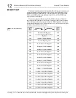
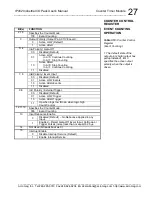
The memory space address map for the IP482 is shown in Table 3.2.
Note that the base address for the IP482 in memory space must be added
to the addresses shown to properly access the IP482 registers. Accesses
are generally performed on a 16-bit basis (D0..D15), but 8-bit (D0..D8) (EO)
accesses are possible in most cases.
EVEN
Base
Addr.+
EVEN Byte
D15 D08
ODD Byte
D07 D00
ODD
Base
Addr.+
00
Board Control Register
01
02
Counters Interrupt Status/Clear
Register
03
04
Counter Trigger Register
05
06
Counter Stop Register
07
08
Counter 1 Control Register
09
0A
Counter 2 Control Register
0B
0C
Counter 3 Control Register
0D
0E
Counter 4 Control Register
0F
10
Counter 5 Control Register
11
12
Counter 6 Control Register
13
14
Counter 7 Control Register
15
16
Counter 8 Control Register
17
18
Counter 9 Control Register
19
1A
Counter 10 Control Register
1B
1C
Counter 1 Read Back Register
1D
1E
Counter 2 Read Back Register
1F
20
Counter 3 Read Back Register
21
22
Counter 4 Read Back Register
23
24
Counter 5 Read Back Register
25
26
Counter 6 Read Back Register
27
28
Counter 7 Read Back Register
29
MEMORY MAP
Table 3.2:
IP482 Memory
Map

