IP482 Industrial I/O Pack User’s Manual Counter Timer Module
__________________________________________________________________
_________________________________________________________________________________________
Acromag, Inc. Tel:248-295-0310 Fax:248-624-9234 Email:[email protected] http://www.acromag.com
24
Watchdog Timer Operation
The watchdog operation counts down from a programmed (Counter
Constant A) value until it reaches 0. While counting, the counter output will
be in its active state (the output polarity is programmable). Upon time-out,
the counter output will return to its inactive state, and an optional interrupt
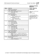
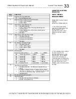
may be generated. Watchdog operation is selected by setting Counter
Control Register bits 2 to 0 to logic “011”.
A timed-out watchdog timer will not re-cycle until it is reloaded and then
followed with a new trigger. Failure to cause a reload would generate an
automatic time-out upon re-triggering, since the counter register will contain
the 0 it previously counted down to.
InA input can be used to reload the counter with the Constant A register
value. InA reload input is enabled via Control register bits 5 and 4. The
counter can also be reloaded via a software write to the Counter Constant A
register. Writing to the Counter Constant A register will load the value
directly into the counter even if watchdog counting is actively counting down.
InB can be used to input an external clock for watchdog timing. Bits 7
and 6 must be set to either logic “01” or “10”. Additionally, the clock source
bits 12, 11, and 10 must be set to logic “101” to enable external clock input.
The timer can alternatively be internally clocked using control register bits
12, 11, and 10. Available frequencies vary depending on carrier opertional
frequency.
InC can be used to either continue/stop watchdog counting or as an
external trigger input. When control register bits 9 and 8 are set to logic
“11”, InC functions as a Continue/Stop signal. When the Continue/Stop
signal is high the counter continues counting (when low the counter stops
counting). Alternate
ly, when control register bits 9 and 8 are set to logic “01”
or “10”, the InC input functions as an external trigger input. The watchdog
timer may also be internally triggered (via the Trigger Control Register at the
base a offset 04H).
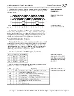
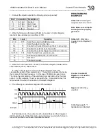
When triggered, the counter/timer contents are decremented by one for
each clock cycle, until it reaches 0, upon which a watchdog timer time-out
occurs. For example, a counter constant value of 30 will provide a time-out
delay of 30 clock cycles of the selected clock. However, due to the
asynchronous relationship between the trigger and the selected clock, one
clock cycle of error can be expected. The counter can be read from the
Counter Read Back register at any time during watchdog operation.
Upon time-out, the counter output pin returns to its inactive state. The
IP482 will also issue an interrupt upon detection of a count value equal to 0,
if enabled via bit-15 of the Counter Control Register. This could be useful
for alerting the host that a watchdog timer time-out has occurred and may
need to be reinitialized. The interrupt will remain pending until the watchdog
timer is reinitialized and the interrupt is released by setting the required bit of
the Counter/Timer Interrupt Status/Clear
register.
COUNTER CONTROL
REGISTER


