IP482 Industrial I/O Pack User’s Manual Counter Timer Module
___________________________________________________________________
________________________________________________________________________________________
Acromag, Inc. Tel:248-295-0310 Fax:248-624-9234 Email:[email protected] http://www.acromag.com
17
Counter Constant B Register (Read/Write)
This read/write register is used to store the counter/timer constant B
value. It is necessary to load the constant value into the counter in one
clock cycle. Thus, a 16-bit write access is required. The addresses
corresponding to the Counter Constant B registers are given in Table 3.2.
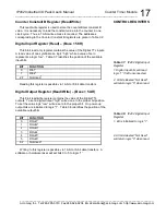
Digital Input Register (Read)
–
(Base + 58H)
This 8-bit read only register contains the value of the Digital TTL inputs.
A read value of one symbolizes a logic “high” while a value of zero
represents a logic “low”. Table 3.7 identifies the position of the available
input bits.
BIT
FUNCTION
0
DIn1
1
1
DIn2
1
2-7
Not Used
2
Reading this register is possible via 16-bit or 8-bit data transfers.
Digital Output Register (Read/Write)
–
(Base + 5AH)
This 8-bit read/write register contains the value of the Digital TTL
outputs. To set a digital output “high” write a one to the proper bit position.
To set the value logic “low” write a zero to the proper bit. On power-up
output bits are initialized to logic "1”. Table 3.8 identifies the position of the
available output bits.
BIT
FUNCTION
0
DOut1
1
1
DOut2
1
2
DOut3
1
3
DOut4
1
4
DOut5
1
5
DOut6
1
6-7
Not Used
2
Writing to this register is possible via 16-bit or 8-bit data transfers. A
software or hardware reset will set bits 0 to 5 to logic “1”.
CONTROL REGISTERS
Table 3.7:
IP482 Digital Input
Register
1.
Digital Input bits will read
logic “1” if left unconnected.
2.
All bits labeled “Not Used”
will return logic “0” when read.
Table 3.8:
IP482 Digital Input
Register
1.
Bit is initialized to logic “1”.
2.
All bits labeled “Not Used”
will return logic “0” when read.

