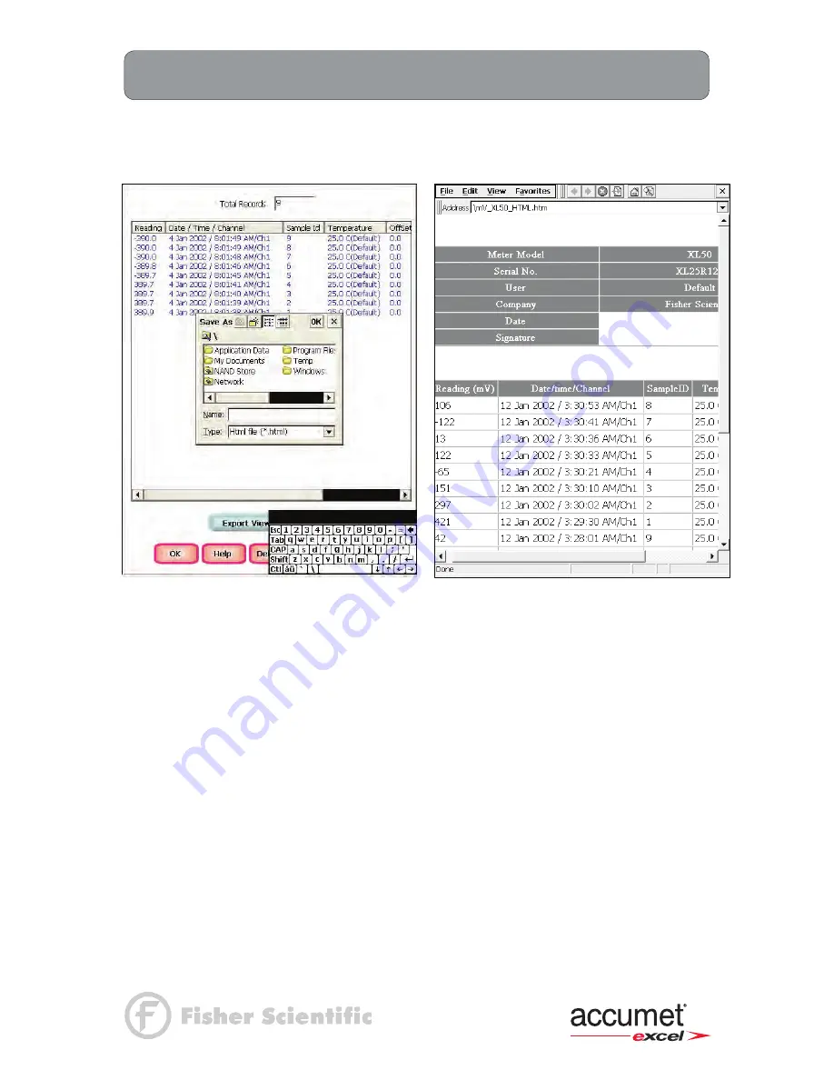
Accumet XL 20 User Manual Download Page 60


49 

mV Setup: 

View Stored Data  

XL15, 20, 25, 50 and 60 meters


Touch 

Export View and Header (or Export View) 

to save your data in HTML format. The file 

can be stored in either the Nand flash, SD Card or any of the other available locations as shown 
in the window. After having selected the path, touch the alphanumeric keypad to name your file. 


Touch the alphanumeric keypad to name 
your file. 

Export view in HTML format 

Summary of Contents for XL 20

Page 1: ......

Page 2: ...Data Storage Criteria 37 Set Display Criteria Setup 38 View Stored Data 39 40 mV Setup mv Setup Screen And Function Buttons 41 Access mv Setup 42 Set Sample ID 43 Set Alarm Limits 44 Set Print Criteri...

Page 3: ...e 85 Select Cell Constant 85 Set Default Temperature 86 Set Reference Temperature 86 Set Temperature Coefficient 87 Set Alarm Limits 87 Set Print Criteria 88 Set Data Storage Criteria 89 Set Display C...

Page 4: ...n 119 Conductivity Operation About Conductivity Measurement 154 Standardizing 155 156 With Auto Buffer Recognition 155 With Manual Buffer Recognition 156 Temperature Standardization 157 Conductivity M...

Page 5: ...n Stability Criteria 55 Set Default Temperature 56 Set Temperature Compensation 57 Set Isopotential Point 57 Set Alarm Limits 57 Set Print Criteria 58 Set Data Storage Criteria 59 Set Display Criteria...

Page 6: ...nt Criteria 97 Set Data Storage Criteria 98 Set Display Criteria 98 View Stored Data 98 TDS Total Dissolved Solids Setup TDS Setup Screen and Function Buttons 99 Access TDS Setup 100 Set SampleID 101...

Page 7: ...Setup OUR Setup Screen and Function Buttons 75 OUR Configuration 78 SOUR Setup SOUR Setup Screen And Function Buttons 79 SOUR Configuration 80 DO Operation STANDARDIZING 135 141 About DO Standardizing...

Page 8: ...ty Setup Conductivity Setup Screen And Function Buttons 81 Access Conductivity Setup 82 Set Sample ID 83 Conductivity Standards 84 Select Standard Recognition 84 Select Stable Indicator 85 Select Auto...

Page 9: ...MENTAL METHODS 125 133 Standardization All Incremental Methods 125 Measurement Known Addition Method 126 127 Measurement Known Subtraction Method 128 129 Measurement Analate Addition Method 130 131 Me...

Page 10: ...sopotential Point 57 Set Alarm Limits 57 Set Print Criteria 58 Set Data Storage Criteria 59 Set Display Criteria 60 View Stored Data 61 62 DO Setup DO Setup Screen and Function Buttons 63 Access DO Se...

Page 11: ...ement Direct Reading with Blank Offset 124 INCREMENTAL METHODS 125 133 Standardization All Incremental Methods 125 Measurement Known Addition Method 126 127 Measurement Known Subtraction Method 128 12...

Page 12: ...pplicable only for XL15 XL20 XL25 XL50 and XL60 Measure ion concentration Applicable only XL25 XL50 and XL60 Measure conductivity resistivity Total Dissolved Solids TDS and salinity Applicable only fo...

Page 13: ...ty 13 620 100 2 cell 1 0 cell constant ATC probe 13 620 19 BOD probe 13 620 SSP with XL60D kit only Meter only includes XL15 XL20 XL25 XL30 XL40 XL50 XL60 meter power supply electrode arm support brac...

Page 14: ...ght 2 8 lb 1000 data pts internal diagnostics yes programmable data storage store on stable time manual programmable data output timed or logged data print interval 3 to 86400 sec programmable alarm y...

Page 15: ...full scale 1 digit Applicable only for XL20 XL30 XL50 and XL60 range 0 to 60 mg L 0 to 1272 mbar 0 to 600 saturation resolution 0 01 mg L 0 1 mbar 0 1 saturation accuracy 0 1 1 least significant digi...

Page 16: ...5 Getting Started XL Series Meters Connectors XL15 and 20 meters 1 Review the layout and arrangement of the rear connector panel XL15 rear connector panel XL20 rear connector panel...

Page 17: ...6 Getting Started XL Series Meters Connectors XL25 and 30 meters XL30 rear connector panel XL25 rear connector panel...

Page 18: ...7 Getting Started XL Series Meters Connectors XL40 and 50 meters XL40 rear connector panel XL50 rear connector panel...

Page 19: ...Series Meters Connectors XL60 meter 2 Connect the electrode arm to the base Electrode base can be attached to either side of meter Purchase additional arm with base 13 637 671 to use both sides XL60...

Page 20: ...er plug into the power outlet or terminal strip 3 Switch power on wall socket or terminal strip 4 Press the black button on the base of the meter for 5 seconds 5 Release the button to power on the met...

Page 21: ...2 pin power plug into the power outlet or terminal strip 3 Switch power on wall socket or terminal strip 4 Press the black button on the base of the meter for 5 seconds 5 Release the button to power...

Page 22: ...n BNC connector Connect the combination pH electrode by plugging it into the BNC input connector twisting to lock in place If a combination electrode isn t used connect the indicating pH electrode int...

Page 23: ...n Always leave the filling hole of liquid filled combination electrodes open Refill when the level of solution gets below the manufacturer s recommended level Store ion specific electrodes according t...

Page 24: ...of the conductivity cell Before using your conductivity cell soak it for 5 to 10 minutes in distilled or deionized water 2 Connect the 2 cell or 4 cell conductivity cell to the conductivity cell jack...

Page 25: ...eplacement Parts section for adapters to allow use of YSI Dissolved Oxygen probes with your accumet meter 1 Carefully review the instruction sheet accompanying the probe for setup and conditioning inf...

Page 26: ...s though self test displays the FISHER Catalog cover briefly displays the desktop screen Home before loading the XL series program which results in the display of the measurement screen Example XL 60...

Page 27: ...design prevents rapid uncontrolled scrolling through the various function screens Function buttons and options change from screen to screen Easy to understand prompts guide you through the operation...

Page 28: ...ibration If the meter is not responding properly to your taps you may need to recalibrate your screen 1 From the HOME screen tap the bottom edge of the screen to access the Task bar Tap Start Settings...

Page 29: ...5 Tap AM or PM Use up and down arrow to select 6 Tap Apply button 7 Tap OK to save the time Setting the Date 1 From the HOME screen tap the bottom left of the screen to access the Start menu Tap Star...

Page 30: ...he bottom right of the screen to access the input panel Tap the Pencil Keyboard icon see below A pop up menu will appear 2 Tap LargeKB to display a large keyboard with all function keys Tap keyboard f...

Page 31: ...Digital SD Expansion Card 1 Close all applications that are using the SD card 2 Remove SD card from the SD slot by slightly pushing down on the card to unlock it 3 When the card disengages and pops up...

Page 32: ...ftware To enter an Internet address URL on your XL series meter 1 From the Start menu tap Programs Internet Explorer Address Bar If the Address Bar is not visible tap the View tab Address Bar to turn...

Page 33: ...s select input parameters and view the software revision and serial number details The Setup button will access the setup screens of the channels that you are currently using The Log Data button sends...

Page 34: ...0 meters only The About button lets you view the software revision and serial number details The Sys Setup button allows you to turn on or off the beep status This is the audible beep that sounds each...

Page 35: ...XL 40 and XL60 meters only The BOD button allows you to enter the BOD Parameter Calculations Screen in the BOD measurement screen available in Channel 4 of the XL 40 and XL60 meters only The OUR butt...

Page 36: ...appear asking you to set a relative mV value or accept the default value of 0 mV This feature may assist the user to standardize certain analytical and monitoring activities such as titration The abs...

Page 37: ...ouch the input channel Ch1 and or Ch3 on the back panel image to select the parameter assigned to that channel Touch the appropriate parameter icon to assign an input to each desired channel XL30 and...

Page 38: ...y mode where all selected screens are shown simultaneously The parameters being displayed is based on the Display Setup see Using the XL Series Meter Display Setup section for directions This is only...

Page 39: ...creen when multiple channels are selected To configure the display 1 Touch the desired Display box 2 Touch any one of the Channel boxes to the right of the display box to assign the channel to the sel...

Page 40: ...ns available in the pH setup mode Function Buttons on pH Setup Screen Touch OK to confirm pH Setup and return to the pH Measure screen Touch Cancel to exit and return to the pH Measure screen without...

Page 41: ...u were in quadruple triple or dual display mode you have access to the Setup mode for each channel displayed Touch the Setup Channel buttons at the top of the screen to toggle back and forth between t...

Page 42: ...e the alphanumeric keypad on the screen to enter the desired Sample ID The BS key will allow you to backspace to remove a character that was incorrectly entered 4 Touch Enter to accept current Sample...

Page 43: ...e a custom buffer group of up to 5 buffers 2 buffer minimum to be used for auto buffer recognition To obtain optimal results it is important to maintain at least 1 pH unit between selected buffers in...

Page 44: ...stable During the standardization procedure you may accept the buffer value before the meter recognizes it as stable by touching the Standardization button To select Buffer Recognition 1 Touch MANUAL...

Page 45: ...ault temperature setting will be displayed on the screen The default temperature can be set from 5 C to 105 C To set Default Temperature 1 Select temperature units by touching the appropriate unit but...

Page 46: ...c keypad to enter the desired mV setting for the new isopotential point 2 Touch Enter to accept this value and return to pH pH FET Setup screen To set Alarm Limits This option allows you to set alarm...

Page 47: ...o the Print Criteria to access the pH Print Criteria Setup screen 2 Touch ON or OFF to change the status of a criteria you want to modify 3 Repeat step 2 for all the remaining criteria except Print In...

Page 48: ...he Touch here to edit button next to the Data Storage Criteria to access the pH Data Storage Setup screen 2 Touch ON or OFF to change the status of a criteria you want to modify 3 Repeat step 1 for al...

Page 49: ...FF appears to the right of the option To set Display Criteria 1 Touch the Touch here to edit button next to the Display Criteria to access the pH Display Criteria Setup screen 2 Touch ON or OFF to cha...

Page 50: ...back to the pH Setup screen from the View Stored Data screen When you touch the Help button information about the current screen appears This information includes step by step instructions for operat...

Page 51: ...save your data in HTML format The file can be stored in either the Nand flash SD Card or any of the other available locations as shown in the window After having selected the path touch the alphanume...

Page 52: ...vailable in the mV setup mode Function buttons on mV Setup Screen Touch OK to confirm mV Setup and return to the mV Measure screen Touch Cancel to exit and return to the mV Measure screen without conf...

Page 53: ...u were in quadruple triple or dual display mode you have access to the Setup mode for each channel displayed Touch the Setup Channel buttons at the top of the screen to toggle back and forth between t...

Page 54: ...hanumeric keypad on the screen to enter the desired Sample ID The BS key will allow you to backspace to remove a character that was incorrectly entered 4 Touch Enter to accept current Sample ID and re...

Page 55: ...r sample measurement was outside of the set limits The Alarm Limit can be set from 2000 0 mV to 2000 0 mV To set Alarm Limits 1 Touch ON or OFF to set the status of the alarm of mV mode 2 Touch the Lo...

Page 56: ...xt to the Print Criteria to access the mV Print Criteria Setup screen 2 Touch ON or OFF to change the status of a criteria you want to modify 3 Repeat step 2 for all the remaining criteria except Prin...

Page 57: ...uch the Touch here to edit button next to the Data Storage Criteria to access the pH Data Storage Setup screen 2 Touch ON or OFF to change the status of a criteria you want to modify 3 Repeat step 2 f...

Page 58: ...f the option It is inactive if OFF appears to the right of the option To set Display Criteria 1 Touch the Touch here to edit button next to the Display Criteria to access the mV Display Criteria Setup...

Page 59: ...rom the View Stored Data screen When you touch the Help button information about the current screen appears This information includes step by step instructions for operating the meter from the current...

Page 60: ...save your data in HTML format The file can be stored in either the Nand flash SD Card or any of the other available locations as shown in the window After having selected the path touch the alphanume...

Page 61: ...de you through the various options available in the Ion setup mode Function Buttons on Ion Setup Screen Touch OK to confirm Ion Setup and return to the Ion Measure screen Touch Cancel to exit and retu...

Page 62: ...were in quadruple triple or dual display mode you have access to the Setup mode for each channel displayed Touch the Setup Channel buttons at the top of the screen to toggle back and forth between the...

Page 63: ...ric keypad on the screen to enter the desired Sample ID The BS key will allow you to backspace to remove a character that was incorrectly entered 4 Touch Enter to accept current Sample ID and return t...

Page 64: ...mple with the ion of interest This reaction removes a fixed amount of the ion of interest from the sample solutions The ion concentration is then calculated based upon the difference in the mV potenti...

Page 65: ...h the Electrode Type box to view the list of electrodes 2 Use the scroll bar to select the desired electrode type Select Measurement Units This screen lets you select the units in which the meter will...

Page 66: ...oncentration To select Auto Read Mode 1 Touch MANUAL or AUTO to choose the desired read mode Set Ion Stability Criteria This setup screen allows you to determine how quickly the meter will respond to...

Page 67: ...order to get the correct concentration value The current default temperature setting will be displayed on the screen The default temperature can be set from 5 C to 105 C To set Default Temperature 1 S...

Page 68: ...n performing ISE experiments it will be necessary to experimentally determine the isopotential point of your own Ion Specific Electrode To set Isopotential Point 1 Touch the Isopotential Point box and...

Page 69: ...o the Print Criteria to access the Ion Print Criteria Setup screen 2 Touch ON or OFF to change the status of a criteria you want to modify 3 Repeat step 2 for all the remaining criteria except Print I...

Page 70: ...e Touch here to edit button next to the Data Storage Criteria to access the pH Data Storage Setup screen 2 Touch ON or OFF to change the status of a criteria you want to modify 3 Repeat step 2 for all...

Page 71: ...OFF appears to the right of the option To set Display Criteria 1 Touch the Touch here to edit button next to the Display Criteria to access the pH Display Criteria Setup screen 2 Touch ON or OFF to ch...

Page 72: ...Stored Data Screen Touch OK to go back to the Ion Setup screen from the View Stored Data screen When you touch the Help button information about the current screen appears This information includes s...

Page 73: ...ve your data in HTML format The file can be stored in either the Nand flash SD Card or any of the other available locations as shown in the window After having selected the path touch the alphanumeric...

Page 74: ...ries Meters Factory Default Settings section for default settings The operating parameters of the DO mode can be set and controlled from the DO setup screen The DO Setup section will guide you through...

Page 75: ...If you were in quadruple triple or dual display mode you have access to the Setup mode for each channel displayed Touch the Setup Channel buttons at the top of the screen to toggle back and forth bet...

Page 76: ...was incorrectly entered 4 Touch Enter to accept current Sample ID and return to the Setup screen To set sample ID Sequential 1 Touch Sequential for sequential Sample ID entry 2 The current ID is disp...

Page 77: ...stable When in the Manual standard recognition mode you must enter the standard value during the standardization procedure The meter will accept the manually entered standard once the measurement is...

Page 78: ...ble indicator speed 1 Touch Fast Med or Slow to select the stability indicator speed Select Auto Read Mode This setup option allows you to select the activity of the Auto read mode If the Auto read is...

Page 79: ...fferent than the current barometric pressure displayed on the XL40 and XL60 you must calibrate the internal barometer See below to set the barometer DO NOT use the barometric pressure issued by the we...

Page 80: ...er on the keypad to accept the salinity value and return to the Setup screen Set Alarm Limits This option allows you to set alarm limits for the DO measuring mode If the DO value of the measurement is...

Page 81: ...nge the status of a criteria you want to modify 3 Repeat step 2 for all the remaining criteria except Print Interval or Print Option 4 In the Print Interval or Print Option Select TIMED to set the des...

Page 82: ...ouch here to edit button next to the Data Storage Criteria to access the DO Data Storage Criteria Setup screen 2 Touch ON or OFF to change the status of a criteria you want to modify 3 Repeat step 2 f...

Page 83: ...e option It is inactive if OFF appears to the right of the option To set Display Criteria 1 Touch the Touch here to edit button next to the Display Criteria to access the Display Criteria Setup screen...

Page 84: ...When touched a dialog box and alphanumeric keypad appear to select a file name and folder to save the html file The saved data can be viewed from the desktop Touch OK to go back to the Setup screen f...

Page 85: ...red in the directory NAND Store SD Card or USB thumb drive After having selected the path touch the alphanumeric keypad to name your file Touch the alphanumeric keypad to name your file Export view in...

Page 86: ...BOD setup mode The main difference is the BOD has a configuration to edit in the setup mode see next page for details Function Buttons on BOD Setup Screen Touch OK to confirm BOD Setup and return to t...

Page 87: ...and Sample Min D O Endpoint 5 Touch OK button to accept the changes of the entire BOD configuration and return to the BOD Setup screen The Seed Minimum Delta DO refers to the difference between the i...

Page 88: ...OUR setup mode The main difference is the OUR has a configuration to edit in the setup mode see next page for details Function Buttons on OUR Setup Screen Touch OK to confirm OUR Setup and return to t...

Page 89: ...n be set from 5 to 60 Minimum ending DO can be set from 0 to 60 To set OUR Configuration 1 Touch the Touch here to edit button next to the OUR Configuration to access the OUR Configuration screen 2 To...

Page 90: ...R setup mode The main difference is the SOUR has a configuration to edit in the setup mode see next page for details Function Buttons on SOUR Setup Screen Touch OK to confirm SOUR Setup and return to...

Page 91: ...g DO can be set from 5 to 60 Minimum ending DO can be set from 0 to 60 To set SOUR Configuration 1 Touch the Touch here to edit button next to the SOUR Configuration to access the OUR Configuration sc...

Page 92: ...various options available in the conductivity setup mode Function Buttons on Conductivity Setup Screen Touch OK to confirm conductivity Setup and return to the conductivity Measure screen Touch Cancel...

Page 93: ...en If you were in quadruple triple or dual display mode you have access to the Setup mode for each channel displayed Touch the Setup Channel buttons at the top of the screen to toggle back and forth b...

Page 94: ...3 Use the alphanumeric keypad on the screen to enter the desired Sample ID The BS key will allow you to backspace to remove a character that was incorrectly entered 4 Touch Enter to accept current Sam...

Page 95: ...em when the meter recognizes the reading as stable When in the Manual standard recognition mode you must enter the buffer value during the standardization procedure The meter will accept the manually...

Page 96: ...elect Cell Constant This setup option allows you to select the appropriate cell constant of the conductivity cell that you are using There are three cell constants to choose from Each is used for a di...

Page 97: ...0 C to 110 C 3 Press Enter in the keypad to return to conductivity Setup screen Set Reference Temperature This setup option allows you to select the reference temperature to be used in the determinati...

Page 98: ...its for the conductivity measuring mode If the conductivity value of the measurement is outside of the boundaries set by the minimum and maximum limits audible and visual warnings will let you know th...

Page 99: ...ton next to the Print Criteria to access the Conductivity Print Criteria Setup screen 2 Touch ON or OFF to change the status of a criteria you want to modify 3 Repeat step 2 for all the remaining crit...

Page 100: ...utton next to the Data Storage Criteria to access the Conductivity Data Storage Criteria Setup screen 2 Touch ON or OFF to change the status of a criteria you want to modify 3 Repeat step 2 for all th...

Page 101: ...n the screen The criteria option is active if ON appears to the right of the option It is inactive if OFF appears to the right of the option To set Display Criteria 1 Touch the Touch here to edit butt...

Page 102: ...Function buttons on View Stored Data Screen Touch OK to go back to the Conductivity Setup screen from the View Stored Data screen When you touch the Help button information about the current screen a...

Page 103: ...to save your data in HTML format The file can be stored in either the Nand flash SD Card or any of the other available locations as shown in the window After having selected the path touch the alphan...

Page 104: ...h the various options available in the resistivity setup mode Function Buttons on Resistivity Setup Screen Touch OK to confirm resistivity Setup and return to the resistivity Measure screen Touch Canc...

Page 105: ...n If you were in quadruple triple or dual display mode you have access to the Setup mode for each channel displayed Touch the Setup Channel buttons at the top of the screen to toggle back and forth be...

Page 106: ...alue Use the multi point standardization option if you are measuring a wide range of samples If a single point calibration is selected there will be only one calibration factor for the entire range of...

Page 107: ...ure to be used in the determination of the resistivity of your sample The reference temperature is the temperature to which the resistivity readings would be normalized The reference temperature can b...

Page 108: ...n 4 Touch Ohm KOhm or MOhm to select resistivity units of low alarm value 5 Touch the High box and use numeric keypad to enter the new limit values 6 Touch Enter on the keypad to accept this limit and...

Page 109: ...of the current display criteria is displayed on the screen The criteria option is active if ON appears to the right of the option It is inactive if OFF appears to the right of the option The Resistivi...

Page 110: ...guide you through the various options available in the TDS setup mode Function Buttons on TDS Setup Screen Touch OK to confirm TDS Setup and return to the TDS Measure screen Touch Cancel to exit and r...

Page 111: ...u were in quadruple triple or dual display mode you have access to the Setup mode for each channel displayed Touch the Setup Channel buttons at the top of the screen to toggle back and forth between t...

Page 112: ...the multi point standardization option if you are measuring a wide range of samples If a single point calibration is selected there will be only one calibration factor for the entire range of operati...

Page 113: ...ature that the meter will use along with the temperature coefficient to calculate a temperature corrected TDS measurement If an ATC probe is used any value entered as a default temperature will be ove...

Page 114: ...Alarm Limits 1 Touch ON or OFF to set the status of the alarm of TDS mode 2 Touch the Low box and use numeric keypad to enter the new limit values 3 Touch Enter on the keypad to accept this limit and...

Page 115: ...of the current display criteria is displayed on the screen The criteria option is active if ON appears to the right of the option It is inactive if OFF appears to the right of the option The TDS Displ...

Page 116: ...u through the various options available in the salinity setup mode Function Buttons on Salinity Setup Screen Touch OK to confirm salinity Setup and return to the salinity Measure screen Touch Cancel t...

Page 117: ...If you were in quadruple triple or dual display mode you have access to the Setup mode for each channel displayed Touch the Setup Channel buttons at the top of the screen to toggle back and forth betw...

Page 118: ...e Use the multi point standardization option if you are measuring a wide range of samples If a single point calibration is selected there will be only one calibration factor for the entire range of op...

Page 119: ...up option allows you to select the reference temperature to be used in the determination of the salinity of your sample The reference temperature can be set from 15 C to 30 C The Salinity Reference Te...

Page 120: ...er on the keypad to accept this limit and return to the salinity Setup screen 4 Touch the High box and use numeric keypad to enter the new limit values 5 Touch Enter on the keypad to accept this limit...

Page 121: ...of the current display criteria is displayed on the screen The criteria option is active if ON appears to the right of the option It is inactive if OFF appears to the right of the option The Salinity...

Page 122: ...uffer recognition activated ON the meter will automatically recognize the buffers from the chosen buffer group and flash the current buffer When the reading is stable you must confirm the buffer In th...

Page 123: ...The meter will return to the pH measure screen 7 Touch Standardize on the pH measure screen to access the standardization screen Repeat process to standardize with up to 5 buffers The efficiency of t...

Page 124: ...tandardization values If the screen says Not standardized proceed to step 5 5 The screen will flash each beaker icon once then a numberic keypad will appear Using the displayed keypad input the value...

Page 125: ...displayed with that of the solution of known temperature Touch the Standardization Temperature box and use numeric keypad to enter the current temperature Press Enter to confirm value 6 Touch OK to c...

Page 126: ...ments of your sample To Measure pH of a Sample with Auto Read ON 1 Immerse the rinsed electrode s in the sample and stir gently 2 Touch Measure to begin measuring your sample The meter will accept the...

Page 127: ...every hour from the start of graphing 1 To view your data in graph format touch Show Graph 2 To start plotting data touch Start Plotting To stop plotting data touch Stop Plotting Once the plotting is...

Page 128: ...be done in either absolute or relative mV In the millivolts mode the current millivolt output from the electrodes being used is monitored and displayed on the screen The meter will continually monitor...

Page 129: ...n option either to adjust the displayed value within a 150 mV window or equate it to zero 1 Access the mV Measure screen from the main screen 2 Immerse the rinsed electrode s in the mV ORP standard so...

Page 130: ...every hour from the start of graphing 1 To view your data in graph format touch Show Graph 2 To start plotting data touch Start Plotting To stop plotting data touch Stop Plotting Once the plotting is...

Page 131: ...he Ion Measure screen displays the direct readout of sample concentration in the desired units as well as the time and date of the last calibration The standards used in the calibration and the slope...

Page 132: ...Measure screen to access the standardization screen 4 Touch Clear if necessary to remove a previous standardization If the screen says Not Standardized proceed to step 5 5 The screen will flash each...

Page 133: ...o this measurement and will not deviate until Meas is touched Repeat steps 1 3 with additional samples Please note that STABLE will only appear if you have completed a successful two point calibration...

Page 134: ...ch Standardize to initiate the standardization process At this point the meter will display the question Is this reading standard or blank 5 Touch STANDARD if the sample that the electrode is immersed...

Page 135: ...on this measurement and will not deviate until Measure is touched again 4 Repeat steps 1 3 with additional samples The meter will update the reading each time Measure is touched Please note that STAB...

Page 136: ...s required in the incremental method calculations which yield the ion concentration of the sample See ISE Theory on Appendix ISE Theory section Make sure you have selected one of the incremental metho...

Page 137: ...ndard volume should not significantly impact the sample volume A 1 100 ratio of standard to sample ratio is optimal For a monovalent electrode the standard addition should result in a 15 30 mV change...

Page 138: ...127 Ion Operation Known Addition Method XL25 50 and 60 meters...

Page 139: ...in order to obtain an ion concentration See ISE Theory on Appendix ISE Theory section Taking a Known Subtraction Measurement 1 Immerse the ion selective electrode in a known volume of the sample solu...

Page 140: ...129 Ion Operation Known Subtraction Method XL25 50 and 60 meters...

Page 141: ...standard solution contain the ionic species of interest See ISE Theory on Appendix ISE Theory section Taking an Analate Addition Measurement 1 Immerse the ion selective electrode in a known volume of...

Page 142: ...131 Ion Operation Analate Addition Method XL25 50 and 60 meters...

Page 143: ...in a known volume of the standard solution 2 Stir the standard 3 Wait for the reading to stabilize STABLE will appear Touch AS to take the first reading 4 Add a known volume of sample solution to the...

Page 144: ...133 Ion Operation Analate Subtraction Method XL25 50 and 60 meters...

Page 145: ...ur from the start of graphing 1 To view your data in graph format touch Show Graph 2 To start plotting data touch Start Plotting To stop plotting data touch Stop Plotting Once the plotting is stopped...

Page 146: ...ter to one or two point calibration in the Setup mode for DO or BOD OUR and SOUR can only calibrated at one point in mg L You also have to use the Setup mode set Auto or Manual calibration available f...

Page 147: ...tion in saturation Refer to the setup section to choose measuring units one or two point standardization and automatic or manual standardization There is no standardization for mbar measuring units No...

Page 148: ...4 3 Touch Clear if you need to delete the previous standardization values 4 Insert DO probe into a BOD bottle filled with 1 inch of water to provide a 100 relative humidity environment 5 Allow probe t...

Page 149: ...llow probe to stabilize for 30 minutes constantly stirring the solution 6 The screen will flash a 0 beaker icon When the reading is stable STABLE appears on the screen Touch Confirm to standardize The...

Page 150: ...ty 25 0 C and 760 mmHg The meter will accept readings below 1 mg L for 0 mg L standardization and 50 of the next standard value 1 Touch Standardize on the DO measure screen to access the standardize s...

Page 151: ...o stabilize for 30 minutes constantly stirring the solution 6 The screen will flash a blank beaker icon for a few seconds then a numeric keypad appears Use the alphanumeric keypad on the screen to ent...

Page 152: ...rent temperature displayed with that of the solution of known temperature Touch the Standardization Temperature box and use numeric keypad to enter the current temperature Press Enter to confirm value...

Page 153: ...ing the setup menu see DO Setup Set Salinity Set Alarm Limits section for details To Measure DO with Auto Read ON 1 Immerse rinsed DO probe into the sample solution constantly stirring the solution 2...

Page 154: ...ed and subtracted from the initial pre incubation dissolved oxygen concentration The difference is a measure of the Biochemical Oxygen Demand BOD of the sample Before measuring BOD remember to setup y...

Page 155: ...ion Parameter Screen 1 Touch BOD on the BOD measurement screen 2 You are now in the BOD Calculation Parameter Screen See To measure BOD of the Sample and To measure BOD of the Seed for instructions Bu...

Page 156: ...robe into a BOD bottle filled with your sample 4 Allow probe to stabilize for 30 minutes constantly stirring the solution 5 Touch BOD on the BOD measurement screen to enter BOD Calculation Parameter S...

Page 157: ...return to the BOD Calculation Parameter Screen 4 After entering the Bottle ID the following text entry boxes will appear and require more information regarding the current sample a Description b Samp...

Page 158: ...ottle ID box 2 Use the alphanumeric keypad to enter the desired Bottle ID The BS key allows you to remove characters that are incorrectly entered 3 Touch Enter to accept current Bottle ID and return t...

Page 159: ...l DO reading and final DO reading must meet the criteria for sample that set under the Set BOD configuration option in Setup mode This condition is only used when calculating the average BOD value If...

Page 160: ...DO reading and final DO reading must meet the criteria for sample that set under the Set BOD configuration option in Setup mode This condition is only used when calculating the average BOD value If th...

Page 161: ...for all available bottle IDs de selection from all selected Bottle ID The selected Bottle ID text box will list all the selected Bottle IDs from the available ID from the result view Button Functions...

Page 162: ...timer expire If you touch the Stop OUR icon before the timer expires you will get a message indicating your measurement reading might not be accurate If you let the timer expire the message states the...

Page 163: ...p SOUR icon or let the timer expire If you touch the Stop SOUR icon before the timer expires you will get a message indicating your measurement reading might not be accurate If you let the timer expir...

Page 164: ...r from the start of graphing 1 To view your data in graph format touch Show Graph 2 To start plotting data touch Start Plotting To stop plotting data touch Stop Plotting Once the plotting is stopped t...

Page 165: ...200 0 x TDS factor ppt Salinity 0 to 0 094 ppt 0 094 to 1 000 ppt 1 000 to 11 50 ppt and 11 50 to 90 00 ppt Before measuring conductivity resistivity TDS or salinity you will need to standardize the m...

Page 166: ...When the reading is stable STABLE appears on the screen Touch Confirm to standardize the buffer The meter will then return to the conductivity measure screen 6 If you selected Single Point in the Setu...

Page 167: ...ardize the meter and then touch Enter The meter now shows the standard value in the flashing beaker 6 When the reading is stable STABLE appears on the screen Touch Confirm to standardize the buffer Th...

Page 168: ...heck the current temperature displayed with that of the solution of known temperature Touch the Standardization Temperature box and use numeric keypad to enter the current temperature Press Enter to c...

Page 169: ...rd the reading once the measurement has become stable STABLE will appear once the meter recognizes that the measurement is stable The meter will automatically change ranges from uS cm to mS cm as requ...

Page 170: ...efreshes every hour from the start of graphing 1 To view your data in graph format touch Show Graph 2 To start plotting data touch Start Plotting To stop plotting data touch Stop Plotting Once the plo...

Page 171: ...the possibility of such damages Each article that Fisher furnishes will conform to the written specifications given in this manual or those of a further improved model Changes are made often to the i...

Page 172: ...Name information by tapping in the appropriate boxes if you are logged in as a user If you are logged in as Admin user ID you can add and delete users Adding User Profiles 1 After logging in under Us...

Page 173: ...mation includes step by step instructions for operating the meter from the current screen Touch Clear to clear all user details Touch Exit to User Profiles screen Touch Apply to current user to apply...

Page 174: ...Default user does not require a password User Login 1 When the meter is turned on the User Login box will appear on the Home screen 2 Select a User ID 3 Touch the Password box use the alphanumeric key...

Page 175: ...figuration All parameters ON Buffer Group USA Sample ID MANUAL Isopotential Point 0 0 mV Print Interval LOG DATA Display Resolution X XX Buffer Recognition AUTO Auto Read Mode MANUAL Temperature Units...

Page 176: ...larm Limit Low 10 00 x 10 7 ION SETUP MODE Alarm Limit High 9 99 x 1010 Display Configuration All parameters ON Print Configuration All parameters ON Data Configuration All parameters ON Sample ID MAN...

Page 177: ...e Indicator ON Cell Constant 1 000 cm Temperature Units C Celsius Default Temperature 25 degree Celsius Reference Temperature 25 degree Celsius Temperature Coefficient 2 100 per degree COND RES TDS SA...

Page 178: ...the XL series meter To print using USB A 1 Power on the XL Series meter and go to single measurement mode 2 Connect HP printer to USB A port on the back of the XL Series meter 3 Enter Sample ID 4 Tap...

Page 179: ...re screen touch Print to initiate the print function 4 The print dialog box is displayed on the screen 5 Select the correct printer using the Printer drop down box selection 6 Set the Port drop down b...

Page 180: ...Touch the My Favorites button to select color setting from your Favorites list Functions buttons on Custom Display Color Setting Screen Touch the Adjust Background Color to define the background colo...

Page 181: ...assigned Setting ID will be listed in My Favorites Color Setting box Functions buttons on My Favorites Color Setting Screen My Favorites Color Setting box displays all the background and text setting...

Page 182: ...nt temperature range as well as operation with an asymmetric electrode system are contemplated However Isopotential correction is never necessary if all measurements will be performed on samples which...

Page 183: ...ated to the effective acid concentration activity of a solution by this defining equation pH log aH3O with a H3O representing the activity or effective concentration of the hydronium ion in solution A...

Page 184: ...In aqueous solutions at 25 C the product H3O OH or the Kw of water must remain constant Therefore an increase in concentration of either term H3O or OH will result in a decrease in the other For exam...

Page 185: ...as Law constant T is the temperature in Kelvin n is the charge on the hydronium ion 1 and F is the Faraday constant pH Meter The pH meter is a sensitive voltmeter capable of accurately measuring small...

Page 186: ...e to sodium ion as well For some pH glasses this means an error as high as 0 5 pH units in highly alkaline high sodium solutions The special FS 5 glass used in Fisher s pH electrodes exhibits much les...

Page 187: ...electrode This millivolt potential is proportional to the activity of the ion of interest and the relationship is defined by the Nernst equation E E 2 3 RT log a where nF E is the measured potential...

Page 188: ...ctrode potential and comparing to those obtained in standard solutions Normally an ionic strength adjustor and or pH adjustor must be added to both the samples and the standards This helps in that the...

Page 189: ...he measured ion is not the same as the one being added via the standard For example a chloride ISE can be immersed in sample for a chloride measurement If a silver standard is added to the sample AgCl...

Page 190: ...ion the ion being measured is in the standard solution and not in the sample solution For example a fluoride standard and a fluoride ISE might be used to measure to aluminum concentration of a sample...

Page 191: ...sses and particularly environmental science and engineering sufficient dissolved oxygen is an absolute requirement for good water quality It is essential for aerobic life and the natural purification...

Page 192: ...al support hotline at 1 888 358 4706 To Perform Replatinization 1 Access the Replatinization mode from the Mode screen In any measuring mode touch Mode to access the Mode screen 2 Touch Replat to ente...

Page 193: ...ell constant of the measuring electrode If the dimensions of the electrodes are such that the area of the parallel plates is very large it is reasonable that more ions can reside between the plates an...

Page 194: ...wo such sensing elements and are designated two cell electrodes The previous discussion has focused on this type of electrode Four cell electrodes are also available and the theory and application of...

Page 195: ...the inner cell one obtains a true picture of conductivity minus the influence of polarization Cell Constant Optimum Conductivity Range 4 cell 0 1 Not Available 1 0 0 01 to 20 mS cm 10 0 1 to 200 mS c...

Page 196: ...NC connector 13 620 531 accuFet XL cone tip electrode 13 620 700 accuFet XL cup tip electrode 13 620 710 accuFet XL flat tip electrode 13 620 720 accuFet XL lance tip electrode 13 620 730 Calibration...

Page 197: ...for adapting YSI model 5910 probes to accumet benchtop meters 13 637 DOADPT Adapter for adapting YSI model 5905 probes to accumet benchtop meters also requires adapter 13 637 DOADPT 13 299 78 BOD Acce...

Page 198: ...esistivity Dissolved Solids 16 oz bottle 100mLx6 bottles 10 mhos 0 1 megohms 6 6 ppm 09 328 1 09 328 6 100 mhos 0 01 megohms 66 ppm 09 328 2 09 328 7 1000 mhos 0 001 megohms 660 ppm 09 328 3 09 328 8...

Page 199: ...t Eutech Instruments distributor or visit our website listed below 68X374204 Rev 6 Dec 07 Manufactured by Eutech Instruments Pte Ltd Blk 55 Ayer Rajah Crescent 04 16 24 Singapore 139949 Tel 65 6778 68...

Reviews: