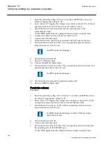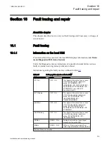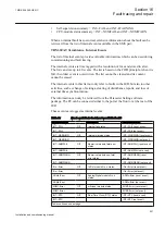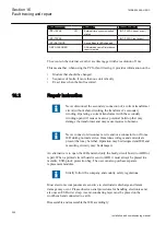
5.
Increase slightly the setting
USet
so that the RAISE output is on the verge of
activation (that is, just below the measured value for bus voltage).
6.
Set
Rline
and
Xline
to values for the maximum line impedance to the load point.
The RAISE output should activate when either
Rline
or
Xline
will be set to
the maximum value. The operation can be checked at the corresponding
binary output and in the event report. If the RAISE output does not activate
reset both
Rline
and
Xline
to
Zero
and set
USet
to a little lower value until the
lower circuit is on the verge of operation.
If the LOWER output activates when either
Rline
or
Xline
have a high setting
the current circuits of the L1 phase are incorrect and must be reversed.
Incorrect current polarity may be an issue with physical wiring or the current
direction convention selected for the CT analogue input as part of the setting
in the Parameter Setting tool. The operation can be checked at the
corresponding binary output and in the event report.
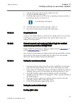
7.
Restore the original connections at the CT in phase L1.
8.
Modify the connections according to step b.
9.
Increase slightly the setting
USet
so that the RAISE output is on the verge of
activation (that is, just below the measured value for bus voltage (UB)).
10. Set
Rline
and
Xline
to values for the maximum line impedance to the load point.
The RAISE output should activate when either
Rline
or
Xline
will be set to
the maximum value. The operation can be checked at the corresponding
binary output and in the event report. If the RAISE output does not activate
reset both
Rline
and
Xline
to
Zero
and set
USet
to a little lower value until the
lower circuit is on the verge of operation.
If the LOWER output activates when either
Rline
or
Xline
have a high setting
the current circuits of the L1 phase are incorrect and must be reversed.
Incorrect current polarity may be an issue with physical wiring or the current
direction convention selected for the CT analogue input as part of the setting
in the Parameter Setting tool. The operation can be checked at the
corresponding binary output and in the event report.
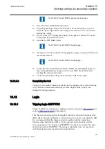
11. Retain the settings for
Rline
and
Xline
to values as the maximum line
impedance to the load point.
12. Decrease slowly the setting of
USet
until the lower circuit is on the verge of
operation (that is, just above the calculated value for load (UL)).
13. Reduce the setting for
XLine
to
Zero
so that the lower circuit operates.
If the operation of Raise and Lower is inverted (Lower instead of Raise and
Raise instead Lower) the current connections have to be reversed in the same
way as for the tests of the Raise component of the voltage regulation with LDC.
14. Modify the CT connections according to (b) and undertake the same test for
the “Lower” of the tap changer with LDC (repeating steps 11 to 13).
15. Restore settings for
Uset
,
RLine
and
XLine
to normal in service values.
16. Restore the original connections at the CT in phase L3.
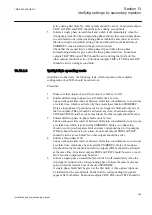
17. After these tests, the single mode voltage control function in the IED can be
taken in to service.
1MRK 504 088-UEN C
Section 14
Primary injection testing
207
Installation and commissioning manual
Summary of Contents for RELION RET670
Page 1: ...Relion 670 series Transformer protection RET670 Installation and commissioning manual...
Page 2: ......
Page 16: ...10...
Page 24: ...18...
Page 26: ...20...
Page 28: ...22...
Page 82: ...76...
Page 88: ...82...
Page 94: ...88...
Page 104: ...98...
Page 110: ...104...
Page 210: ...204...
Page 230: ...224...
Page 239: ...233...


