


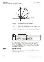


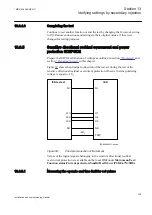

Table 23:
Test points for phase-to-phase loops L1–L2
Test point
Value
Comments
1
X
X1
R
0
2
X
0
R
RLdFw
3
X
0.85·X1
R=0.491·X1+0.5 RFFwPP
R
0.85·X1·1/tan(60°)+0.5 RFFwPP
4
X
0.85·X1
R
-0.85·X1·tan (AngNegRes-90°)
5
X
0.5·RFFwPP·tan (ArgLd)
R
0.5·RFFwPP
6
X
-0.5·RLdFw·tan (ArgDir)
R
0.5·RLdFw
The table showing test points for phase-to-phase loops is used together with figure
13.5.2.1
Measuring the operate limit of set values
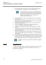
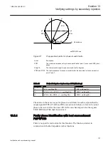
1.
Supply the IED with healthy conditions for at least two seconds.
2.
Apply the fault condition and slowly decrease the measured impedance to
find the operate value for of the phase-to-earth loop L3, test point 1,
according to figure
. Compare the result of the measurement with the
expected value according to table
The corresponding binary signals that inform about the operation of the phase
selection measuring elements are available in the local HMI under
Main menu/Test/Function status/Impedance Protection/
PhaseSelection(PDIS, 21)/PHSx
.
3.
to
to find the operate values for the remaining test points
.
When the load encroachment characteristic is deliberately set
very high in order not to have an influence, then the test points
2 and 5 can be replaced by test point 7.
4.
to
to find the operate value for the phase-to-phase fault in L1
— L2 according to figure
and table
.
Section 13
1MRK 504 088-UEN C
Verifying settings by secondary injection
124
Installation and commissioning manual
Summary of Contents for RELION RET670
Page 1: ...Relion 670 series Transformer protection RET670 Installation and commissioning manual...
Page 2: ......
Page 16: ...10...
Page 24: ...18...
Page 26: ...20...
Page 28: ...22...
Page 82: ...76...
Page 88: ...82...
Page 94: ...88...
Page 104: ...98...
Page 110: ...104...
Page 210: ...204...
Page 230: ...224...
Page 239: ...233...


