


13.5
Impedance protection
13.5.1
Distance protection zones, quadrilateral characteristic
ZMQPDIS
Prepare the IED for verification of settings as outlined in section
and
in this chapter.
Consider releasing Zone 1, the Phase selection with load encroachment,
quadrilateral characteristic (FDPSDPIS) and the tripping logic SMPPTRC. If the
autorecloser is not released and in service, trip will always be three phase.
Measure operating characteristics during constant current conditions. Keep the
measured current as close as possible to its rated value or lower. But make sure it is
higher than 30% of the rated current.
Ensure that the maximum continuous current in an IED does not exceed four times
its rated value, if the measurement of the operating characteristics runs under
constant voltage conditions.
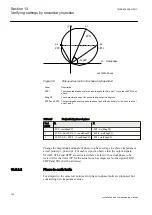
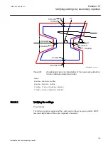
The test procedure has to take into consideration that the shaped load encroachment
characteristic is active. It is therefore necessary to check the setting. To verify the
settings with the shaped load encroachment characteristic the test should be carried
out according to figures
. In cases where the load
encroachment characteristic is activated tests according to the adjusted figures
should be carried out.
To verify the settings for the operating points according to the following fault types
should be tested:
•
One phase-to-phase fault
•
One phase-to-earth fault
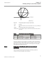
The shape of the operating characteristic depends on the values of the setting
parameters.
The figures illustrating the characteristic for the distance protection
function can be used for settings with and without load
encroachment. The solid lines designate the diagram applicable
when the load current compensation
operationLdCom
parameter is
set to 1 (On). This is the default setting. The solid line and all test
points except 13 are valid for this setting.
When it is set to 0 (Off) then the dotted lines and test point 13 are
valid. Test points 5, 6, and 7 are not valid for this measurement.
1MRK 504 088-UEN C
Section 13
Verifying settings by secondary injection
117
Installation and commissioning manual
Summary of Contents for RELION RET670
Page 1: ...Relion 670 series Transformer protection RET670 Installation and commissioning manual...
Page 2: ......
Page 16: ...10...
Page 24: ...18...
Page 26: ...20...
Page 28: ...22...
Page 82: ...76...
Page 88: ...82...
Page 94: ...88...
Page 104: ...98...
Page 110: ...104...
Page 210: ...204...
Page 230: ...224...
Page 239: ...233...


