


The capability of a transformer (or generator) to withstand overexcitation can be
illustrated in the form of a thermal capability curve, that is, a diagram which shows the
permissible time as a function of the level of over-excitation. When the transformer is
loaded, the induced voltage and hence the flux density in the core can not be read off
directly from the transformer terminal voltage. Normally, the leakage reactance of each
separate winding is not known and the flux density in the transformer core can then not
be calculated. In two-winding transformers, the low voltage winding is normally
located close to the core and the voltage across this winding reflects the flux density in
the core. However, depending on the design, the flux flowing in the yoke may be
critical for the ability of the transformer to handle excess flux.
The Overexcitation protection (OEXPVPH, 24) has current inputs to allow calculation
of the load influence on the induced voltage. This gives a more exact measurement of
the magnetizing flow. For power transformers with unidirectional load flow, the
voltage to OEXPVPH (24) should therefore be taken from the feeder side.
Heat accumulated in critical parts during a period of overexcitation will be reduced
gradually when the excitation returns to the normal value. If a new period of
overexcitation occurs after a short time interval, the heating will start from a higher
level, therefore, OEXPVPH (24) must have thermal memory. A fixed cooling time
constant is settable within a wide range.
The general experience is that the overexcitation characteristics for a number of power
transformers are not in accordance with standard inverse time curves. In order to make
optimal settings possible, a transformer adapted characteristic is available in the IED.
The operate characteristic of the protection function can be set to correspond quite well
with any characteristic by setting the operate time for six different figures of
overexcitation in the range from 100% to 180% of rated V/Hz.
When configured to a single phase-to-phase voltage input, a corresponding phase-to-
phase current is calculated which has the same phase angle relative the phase-to-phase
voltage as the phase currents have relative the phase voltages in a symmetrical system.
The function should preferably be configured to use a three-phase voltage input if
available. It then uses the positive sequence quantities of voltages and currents.
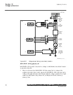
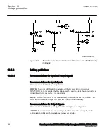
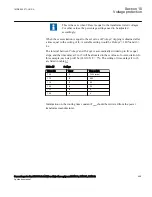
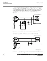
Analog measurements shall not be taken from any winding where a
load tap changer is located.
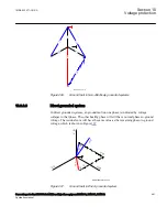
Some different connection alternatives are shown in figure
.
1MRK 502 071-UUS A
Section 10
Voltage protection
Generator protection REG670 2.2 ANSI and Injection equipment REX060, REX061, REX062
455
Application manual
Summary of Contents for RELION 670 SERIES REG670
Page 1: ...RELION 670 SERIES Generator protection REG670 Version 2 2 ANSI Application manual ...
Page 2: ......
Page 44: ...38 ...
Page 66: ...60 ...
Page 102: ...96 ...
Page 200: ...194 ...
Page 442: ...436 ...
Page 486: ...480 ...
Page 508: ...502 ...
Page 514: ...508 ...
Page 524: ...518 ...
Page 658: ...652 ...
Page 736: ...730 ...
Page 774: ...768 ...
Page 828: ...822 ...
Page 829: ...823 ...


