


Wearing of the tap changer contacts
SEMOD159053-376 v4
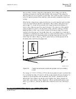
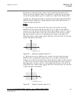
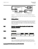
Two counters, ContactLife and NoOfOperations are available within the Tap changer
control and supervision function, 6 binary inputs TCMYLTC or 32 binary inputs
TCLYLTC (84). They can be used as a guide for maintenance of the tap changer
mechanism. The ContactLife counter represents the remaining number of operations
(decremental counter) at rated load.
ContactLife
ContactLife
n+1
n
Irated
Iload
a
æ
ö
=
- ç
÷
ç
÷
è
ø
EQUATION1873 V2 EN-US
(Equation 269)
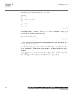
where n is the number of operations and α is an adjustable setting parameter,
CLFactor
, with default value is set to 2. With this default setting an operation at rated
load (current measured on HV-side) decrements the ContactLife counter with 1.
The NoOfOperations counter simply counts the total number of operations
(incremental counter).
Both counters are stored in a non-volatile memory as well as, the times and dates of
their last reset. These dates are stored automatically when the command to reset the
counter is issued. It is therefore necessary to check that the IED internal time is correct
before these counters are reset. The counter value can be reset on the local HMI under
Main menu/Reset/Reset counters/TransformerTapControl(YLTC,84)/TCMYLTC:
1 or TCLYLTC:1/Reset Counter and ResetCLCounter
Both counters and their last reset dates are shown on the local HMI as service values
under
Main menu/Test/Function status/Control/TransformerTapControl(YLTC,
84)/TCMYLTC:x/TCLYLTC:x/CLCNT_VAL
and
Main menu/Test/Function status/
Control/TransformerTapControl (YLTC,84)/TCMYLTC:x/TCLYLTC:x/
CNT_VAL
15.4.2
Setting guidelines
SEMOD171503-1 v1
15.4.2.1
TR1ATCC or TR8ATCC general settings
SEMOD171501-4 v3
TrfId
: The transformer identity is used to identify transformer individuals in a parallel
group. Thus, transformers that can be part of the same parallel group must have unique
identities. Moreover, all transformers that communicate over the same horizontal
communication (GOOSE) must have unique identities.
Xr2
: The reactance of the transformer in primary ohms referred to the LV side.
1MRK 502 071-UUS A
Section 15
Control
Generator protection REG670 2.2 ANSI and Injection equipment REX060, REX061, REX062
631
Application manual
Summary of Contents for RELION 670 SERIES REG670
Page 1: ...RELION 670 SERIES Generator protection REG670 Version 2 2 ANSI Application manual ...
Page 2: ......
Page 44: ...38 ...
Page 66: ...60 ...
Page 102: ...96 ...
Page 200: ...194 ...
Page 442: ...436 ...
Page 486: ...480 ...
Page 508: ...502 ...
Page 514: ...508 ...
Page 524: ...518 ...
Page 658: ...652 ...
Page 736: ...730 ...
Page 774: ...768 ...
Page 828: ...822 ...
Page 829: ...823 ...


