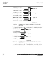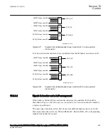
control (QCBAY), Local remote (LOCREM) and Local remote control
(LOCREMCTRL) are used.
Information about the control location is given to TR1ATCC (90) or TR8ATCC (90)
function through connection of the Permitted Source to Operate (PSTO) output of the
QCBAY function block to the input PSTO of the TR1ATCC (90) or TR8ATCC (90)
function block.
Control Mode
SEMOD159053-35 v4
The control mode of the automatic voltage control for tap changer function, TR1ATCC
(90) for single control and TR8ATCC (90) for parallel control can be:
•
Manual
•
Automatic
The control mode can be changed from the local location via the command menu on
the local HMI under
Main menu/Control/Commands/
TransformerVoltageControl(ATCC,90)/TR1ATCC:x/TR8ATCC:x
, or changed
from a remote location via binary signals connected to the MANCTRL, AUTOCTRL
inputs on TR1ATCC (90) or TR8ATCC (90) function block.
Measured Quantities
SEMOD159053-61 v4
In normal applications, the LV side of the transformer is used as the voltage measuring
point. If necessary, the LV side current is used as load current to calculate the line-
voltage drop to the regulation point.
Automatic voltage control for tap changer, TR1ATCC (90) for single control and
TR8ATCC (90) for parallel control function block has three inputs I3P1, I3P2 and
V3P2 corresponding to HV-current, LV-current and LV-voltage respectively. These
analog quantities are fed to the IED via the transformer input module, the Analog to
Digital Converter and thereafter a Pre-Processing Block. In the Pre-Processing Block, a
great number of quantities for example, phase-to-phase analog values, sequence values,
max value in a three phase group etc., are derived. The different function blocks in the
IED are then “subscribing” on selected quantities from the pre-processing blocks. In
case of TR1ATCC (90) or TR8ATCC (90), there are the following possibilities:
SEMOD159053-65 v6
•
I3P1 represents a three-phase group of phase current with the highest current in
any of the three phases considered. As only the highest of the phase current is
considered, it is also possible to use one single-phase current as well as two-phase
currents. In these cases, the currents that are not used will be zero.
•
For I3P2 and V3P2 the setting alternatives are: any individual phase current/
voltage, as well as any combination of phase-phase current/voltage or the positive
sequence current/voltage. Thus, single-phase as well as, phase-phase or three-
phase feeding on the LV-side is possible but it is commonly selected for current
and voltage.
Section 15
1MRK 502 071-UUS A
Control
598
Generator protection REG670 2.2 ANSI and Injection equipment REX060, REX061, REX062
Application manual
Summary of Contents for RELION 670 SERIES REG670
Page 1: ...RELION 670 SERIES Generator protection REG670 Version 2 2 ANSI Application manual ...
Page 2: ......
Page 44: ...38 ...
Page 66: ...60 ...
Page 102: ...96 ...
Page 200: ...194 ...
Page 442: ...436 ...
Page 486: ...480 ...
Page 508: ...502 ...
Page 514: ...508 ...
Page 524: ...518 ...
Page 658: ...652 ...
Page 736: ...730 ...
Page 774: ...768 ...
Page 828: ...822 ...
Page 829: ...823 ...

