The threshold voltages
VDeadBusEnerg
and
VDeadLineEnerg
, have to be set to a
value greater than the value where the network is considered not to be energized. A
typical value can be 40% of the base voltages.
A disconnected line can have a considerable potential due to, for
instance, induction from a line running in parallel, or by being fed via
the extinguishing capacitors in the circuit breakers. This voltage can be
as high as 30% or more of the base line voltage.
Because the setting ranges of the threshold voltages
VLiveBusEnerg
/
VLiveLineEnerg
and
VDeadBusEnerg
/
VDeadLineEnerg
partly overlap each other, the setting conditions
may be such that the setting of the non-energized threshold value is higher than that of
the energized threshold value. The parameters must therefore be set carefully to avoid
overlapping.
VMaxEnerg
This setting is used to block the closing when the voltage on the live side is above the
set value of
VMaxEnerg
.
tAutoEnerg
and
tManEnerg
The purpose of the timer delay settings,
tAutoEnerg
and
tManEnerg
, is to ensure that
the dead side remains de-energized and that the condition is not due to a temporary
interference. Should the conditions not persist for the specified time, the delay timer is
reset and the procedure is restarted when the conditions are fulfilled again. Circuit
breaker closing is thus not permitted until the energizing condition has remained
constant throughout the set delay setting time.
15.2
Apparatus control APC
IP14560-1 v2
15.2.1
Application
IP14931-1 v1
M13443-4 v13
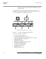
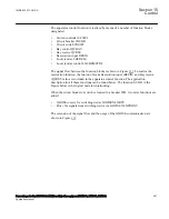
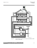
The apparatus control is a functionality for control and supervising of circuit breakers,
disconnectors, and grounding switches within a bay. Permission to operate is given
after evaluation of conditions from other functions such as interlocking, synchronism
check, operator place selection and external or internal blockings.
The complete apparatus control function is not included in this product,
and the information below is included for understanding of the
1MRK 502 071-UUS A
Section 15
Control
Generator protection REG670 2.2 ANSI and Injection equipment REX060, REX061, REX062
539
Application manual
Summary of Contents for RELION 670 SERIES REG670
Page 1: ...RELION 670 SERIES Generator protection REG670 Version 2 2 ANSI Application manual ...
Page 2: ......
Page 44: ...38 ...
Page 66: ...60 ...
Page 102: ...96 ...
Page 200: ...194 ...
Page 442: ...436 ...
Page 486: ...480 ...
Page 508: ...502 ...
Page 514: ...508 ...
Page 524: ...518 ...
Page 658: ...652 ...
Page 736: ...730 ...
Page 774: ...768 ...
Page 828: ...822 ...
Page 829: ...823 ...

