


Regardless which one of the above two options is selected, busbar differential
protection will behave correctly.
The main CT ratios must also be set. This is done by setting the two parameters
CTsec
and
CTprim
for each current channel. For a 1000/5 A CT, the following settings shall
be used:
•
CTprim
=
1000
(value in A)
•
CTsec
=
5
(value in A).
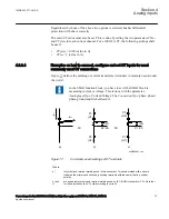
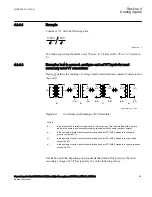
4.2.2.4
Examples on how to connect, configure and set CT inputs for most
commonly used CT connections
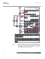
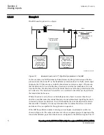
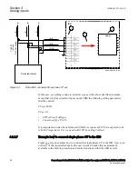
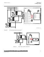
SEMOD55055-296 v7
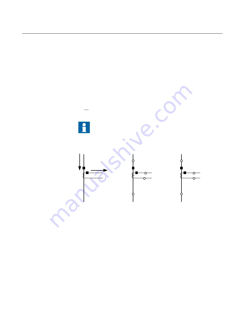
Figure
defines the marking of current transformer terminals commonly used around
the world:
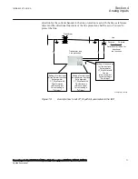
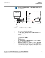
In the SMAI function block, you have to set if the SMAI block is
measuring current or voltage. This is done with the parameter:
AnalogInputType
: Current/Voltage. The
ConnectionType
: phase -phase/
phase-ground and
GlobalBaseSel
.
I
Sec
I
P
ri
S1 (X1)
P1
(H1)
P2
(H2)
S2 (X2)
P2
(H2)
P1
(H1)
x
x
a)
b)
c)
en06000641.vsd
S2 (X2)
S1 (X1)
IEC06000641 V1 EN-US
Figure 17:
Commonly used markings of CT terminals
Where:
a)
is symbol and terminal marking used in this document. Terminals marked with a square
indicates the primary and secondary winding terminals with the same (that is, positive)
polarity
b) and
c)
are equivalent symbols and terminal marking used by IEC (ANSI) standard for CTs. Note that
for these two cases the CT polarity marking is correct!
1MRK 502 071-UUS A
Section 4
Analog inputs
Generator protection REG670 2.2 ANSI and Injection equipment REX060, REX061, REX062
73
Application manual
Summary of Contents for RELION 670 SERIES REG670
Page 1: ...RELION 670 SERIES Generator protection REG670 Version 2 2 ANSI Application manual ...
Page 2: ......
Page 44: ...38 ...
Page 66: ...60 ...
Page 102: ...96 ...
Page 200: ...194 ...
Page 442: ...436 ...
Page 486: ...480 ...
Page 508: ...502 ...
Page 514: ...508 ...
Page 524: ...518 ...
Page 658: ...652 ...
Page 736: ...730 ...
Page 774: ...768 ...
Page 828: ...822 ...
Page 829: ...823 ...


