119
Synchrocheck and energizing check (SYN)
Chapter 13
Verifying settings by secondary
injection
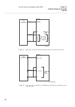
Table 17:
Voltage to input
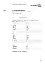
Table 18:
Binary inputs SYN1, SYN2 and SYN3
Table 19:
Binary outputs SYN1, SYN2, SYN3
12.5
Completing the test
Continue to test another function or complete the test by setting the test mode to off.
Signal
SYN1
SYN2
SYN3
BUS1 U5
H
H
H
H
H
H
-
-
H
L
H
H
H
H
H
H
BUS2 U4
-
-
-
-
H
L
-
-
H
H
-
-
-
-
H
L
LINE1 UL1
H
L
-
-
-
-
H
L
-
-
H
L
-
-
-
-
LINE2 UL2
-
-
H
L
-
-
H
H
-
-
-
-
H
L
-
-
Signal
SYN1
SYN2
SYN3
FD1CLD
1
1
0
0
0
0
1
1
0
0
0
0
1
1
1
1
FD1OPEN
0
0
1
1
1
1
0
0
1
1
1
1
0
0
0
0
FD2CLD
0
0
1
1
1
1
1
1
0
0
1
1
0
0
0
0
FD2OPEN
1
1
0
0
0
0
0
0
1
1
0
0
1
1
1
1
CB1CLD
-
-
-
-
-
-
1
1
1
1
1
1
1
1
1
1
CB1OPEN
-
-
-
-
-
-
0
0
0
0
0
0
0
0
0
0
CB2CLD
0
0
1
1
0
0
-
-
-
-
0
0
1
1
0
0
CB2OPEN
1
1
0
0
1
1
-
-
-
-
1
1
0
0
1
1
CB3CLD
1
1
1
1
1
1
1
1
1
1
-
-
-
-
-
-
CB3OPEN
0
0
0
0
0
0
0
0
0
0
-
-
-
-
-
-
Signal
SYN1
SYN2
SYN3
VSUF1
1
1
0
0
0
0
1
1
0
0
0
0
1
1
0
0
VSUF2
0
0
1
1
0
0
1
1
0
0
1
1
0
0
0
0
VSUB1
-
-
-
-
-
-
0
0
1
1
0
0
0
0
1
1
VSUB2
0
0
0
0
1
1
0
0
1
1
-
-
-
-
-
-
AUTOOK
1
0
1
0
1
0
1
0
1
0
1
0
1
0
1
0
Summary of Contents for REB 551-C3*2.5
Page 9: ...Contents ...
Page 21: ...12 Introduction to the installation and commissioning manual Chapter 1 Introduction ...
Page 27: ...18 Note signs Chapter 2 Safety information ...
Page 53: ...44 Installing the 56 64 kbit data communication cables Chapter 5 Installing the terminal ...
Page 59: ...50 Checking the binary I O circuits Chapter 6 Checking the external circuitry ...
Page 147: ...138 Repair support Chapter 16 Fault tracing and repair ...


