98
Fuse failure supervision (FUSE)
Chapter 13
Verifying settings by secondary
injection
8
Fuse failure supervision (FUSE)
Prepare the terminal for verification of settings as outlined in
sectction 2 "Preparing for test"
this chapter.
The verification is divided in two main parts. The first part is common to all fuse failure super-
vision options, and checks that binary inputs and outputs operate as expected according to actual
configuration. In the second part the relevant set operate values are measured.
The corresponding binary signals that inform the operator about the operation of the FUSE func-
tion are available on the local human-machine interface (HMI) unit under the menu:
Service Report/Functions/FuseFailure/FuncOutputs
8.1
Checking that the binary inputs and outputs
operate as expected
Procedure
1.
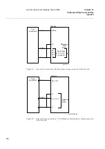
Simulate normal operating conditions with the three-phase currents
in phase with their corresponding phase voltages and with all of
them equal to their rated values.
2.
Connect the nominal dc voltage to the FUSE-DISC binary input.
•
The signal FUSE-VTSU should appear with almost no time delay.
•
No signals FUSE-VTSZ and FUSE-VTF3PH should appear on the
terminal.
•
Only the distance protection function operates.
•
No other undervoltage-dependent functions must operate.
3.
Disconnect the dc voltage from the FUSE-DISC binary input terminal.
4.
Connect the nominal dc voltage to the FUSE-MCB binary input.
•
The FUSE-VTSU and FUSE-VTSZ signals should appear without
any time delay.
•
No undervoltage-dependent functions must operate.
5.
Disconnect the dc voltage from the FUSE-MCB binary input terminal.
6.
Disconnect one of the phase voltages and observe the logical output
signals on the terminal binary outputs.
FUSE-VTSU and FUSE-VTSZ signals should simultaneously appear.
7.
After more than 5 seconds disconnect the remaining two phase volt-
ages and all three currents.
•
There should be no change in the high status of the output signals
FUSE-VTSU and FUSE-VTSZ.
•
The signal FUSE-VTF3PH will appear.
Summary of Contents for REB 551-C3*2.5
Page 9: ...Contents ...
Page 21: ...12 Introduction to the installation and commissioning manual Chapter 1 Introduction ...
Page 27: ...18 Note signs Chapter 2 Safety information ...
Page 53: ...44 Installing the 56 64 kbit data communication cables Chapter 5 Installing the terminal ...
Page 59: ...50 Checking the binary I O circuits Chapter 6 Checking the external circuitry ...
Page 147: ...138 Repair support Chapter 16 Fault tracing and repair ...

