


107
Synchrocheck and energizing check (SYN)
Chapter 13
Verifying settings by secondary
injection
12.1
Testing the phasing function
(Applicable only if the phasing function is included in the terminal.)
These voltage inputs are used:
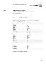
The settings in
table 9
can be used during the test if the final setting is not determined.
Table 9:
Test settings for phasing
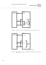
The settings are located in the local HMI under:
U-line
UL1, UL2 or UL3 voltage input on the terminal.
U-bus
U5 voltage input on the terminal
Parameter
Setting
Operation
Off
InputPhase
UL1
PhaseShift
0 deg
URatio
1.00
USelection
SingleBus
AutoEnerg
Off
ManEnerg
Off
ManDBDL
Off
UHigh
70% U1b
ULow
40% U1b
FreqDiff
0.05 Hz
PhaseDiff
45
°
UDiff
30% U1b
tAutoEnerg
0.5 s
tManEnerg
0.5 s
OperationSynch
On
ShortPulse
Off
FreqDiffSynch
0.40 Hz
tPulse
0.20 s
tBreaker
0.20 s
VTConnection
Line
tSync
Os
FreqDiffBlock
Off
Summary of Contents for REB 551-C3*2.5
Page 9: ...Contents ...
Page 21: ...12 Introduction to the installation and commissioning manual Chapter 1 Introduction ...
Page 27: ...18 Note signs Chapter 2 Safety information ...
Page 53: ...44 Installing the 56 64 kbit data communication cables Chapter 5 Installing the terminal ...
Page 59: ...50 Checking the binary I O circuits Chapter 6 Checking the external circuitry ...
Page 147: ...138 Repair support Chapter 16 Fault tracing and repair ...