


37
Installing the serial communication cable for
RS485 SPA/IEC
Chapter 5
Installing the terminal
5
Installing the serial communication cable for
RS485 SPA/IEC
5.1
RS485 serial communication module
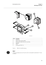
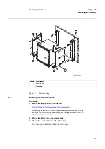
Figure 8:
Pin arrangement on modem terminal. Baud rate: 9600
The distance between earth points should be < 100 m, see
figure 9
. Only the outer shielding is
connected to the protective earth at the terminal. The inner and outer shieldings are connected
to the protective earth at the external equipment. Use insulating tape for the inner shield to pre-
vent contact with the protective earth. Make sure that the terminals are properly earthed with as
short connections as possible from the earth screw, for example to an earthed frame.
The terminal and the external equipment should preferably be connected to the same battery.
Where:
A
Signal A
B
Signal B
1)
Do not use
GND
Ground
en03000109.vsd
A
B
1)
1)
1)
GND
Up
Summary of Contents for REB 551-C3*2.5
Page 9: ...Contents ...
Page 21: ...12 Introduction to the installation and commissioning manual Chapter 1 Introduction ...
Page 27: ...18 Note signs Chapter 2 Safety information ...
Page 53: ...44 Installing the 56 64 kbit data communication cables Chapter 5 Installing the terminal ...
Page 59: ...50 Checking the binary I O circuits Chapter 6 Checking the external circuitry ...
Page 147: ...138 Repair support Chapter 16 Fault tracing and repair ...