118
Synchrocheck and energizing check (SYN)
Chapter 13
Verifying settings by secondary
injection
2.
Apply signals according to the tables and verify that correct output
signals are generated.
Table 14:
Voltages
Table 15:
Binary inputs
Table 16:
Binary outputs
12.4.2
Testing the voltage selection for 1 1/2 circuit breaker diameter
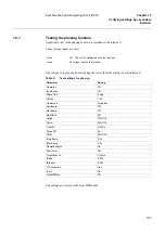
This test should verify that correct voltage is selected for the measurement in the energizing
function used for a diameter in a one and a half breaker arrangement. Apply single-phase volt-
ages to the inputs according to the tables below. “H” means a voltage of 100% U1b and “L”
means a voltage of 30% U1b. Verify that correct output signals are generated.
1.
Connect the signals below to binary inputs and binary outputs.
2.
Apply signals according to the tables and verify that correct output
signals are generated.
Signal
Voltage from bus1 U5
1
1
1
1
1
1
1
0
0
0
0
0
0
0
Voltage from bus2 U4
0
0
0
0
0
0
0
1
1
1
1
1
1
1
Signal
CB1OPEN
1
0
0
0
0
0
1
0
0
1
1
1
1
0
CB1CLD
0
1
1
1
1
1
0
1
1
0
0
0
0
1
CB2OPEN
1
1
1
1
1
0
0
1
0
0
0
0
0
0
CB2CLD
0
0
0
0
0
1
1
0
1
1
1
1
1
1
UB1FF
0
0
1
0
0
0
0
0
0
0
1
0
0
0
UB2FF
0
0
0
1
0
0
0
0
0
0
0
1
0
0
VTSU
0
0
0
0
1
0
0
0
0
0
0
0
1
0
Signal
AUTOOK
1
1
0
1
0
1
0
0
0
1
1
0
0
0
MANOK
1
1
0
1
0
1
0
0
0
1
1
0
0
0
VSUB1
1
1
1
1
1
1
0
1
1
0
0
0
0
1
VSUB2
0
0
0
0
0
0
1
0
0
1
1
1
1
0
Summary of Contents for REB 551-C3*2.5
Page 9: ...Contents ...
Page 21: ...12 Introduction to the installation and commissioning manual Chapter 1 Introduction ...
Page 27: ...18 Note signs Chapter 2 Safety information ...
Page 53: ...44 Installing the 56 64 kbit data communication cables Chapter 5 Installing the terminal ...
Page 59: ...50 Checking the binary I O circuits Chapter 6 Checking the external circuitry ...
Page 147: ...138 Repair support Chapter 16 Fault tracing and repair ...


