


109
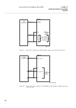
Synchrocheck and energizing check (SYN)
Chapter 13
Verifying settings by secondary
injection
12.2.2
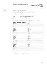
Testing the voltage difference
Set the voltage difference at 30% U1b on the HMI, and the test should check that operation is
achieved when the voltage difference UDiff is lower than 30% U1b.
The settings in
table 10
can be used during the test if the final setting is not determined.
Table 10:
Test settings for voltage difference (NA=Not applicable)
U5
Activate SYN2_CB1CLD
SYN3
U-line
UL1
Activate SYN3_CB2CLD
UL2
Activate SYN3_FD2CLD
U5
Activate SYN3_CB1CLD and CB2CLD
U-bus
U4
No activation of inputs necessary
Parameter
Setting
Single bay
Single bay
with phas-
ing
Multiple
bays
Operation
On
InputPhase
UL1
UMeasure
Ph/N
NA
NA
PhaseShift
0 deg
URatio
1.00
USelection
SingleBus
AutoEnerg
Off
ManEnerg
Off
ManDBDL
Off
UHigh
70% U1b
ULow
40% U1b
FreqDiff
0,05 Hz
PhaseDiff
45
°
UDiff
30% U1b
tAutoEnerg
0.5 s
tManEnerg
0.5 s
OperationSynch
Off
NA
NA
ShortPulse
Off
NA
NA
FreqDiffSynch
0.4 Hz
NA
NA
tPulse
0.2 s
NA
NA
tBreaker
0.2 s
NA
NA
VTConnection
Line
NA
tSync
Os
FreqDiffBlock
Off
NA
NA
Summary of Contents for REB 551-C3*2.5
Page 9: ...Contents ...
Page 21: ...12 Introduction to the installation and commissioning manual Chapter 1 Introduction ...
Page 27: ...18 Note signs Chapter 2 Safety information ...
Page 53: ...44 Installing the 56 64 kbit data communication cables Chapter 5 Installing the terminal ...
Page 59: ...50 Checking the binary I O circuits Chapter 6 Checking the external circuitry ...
Page 147: ...138 Repair support Chapter 16 Fault tracing and repair ...