


108
Synchrocheck and energizing check (SYN)
Chapter 13
Verifying settings by secondary
injection
Settings/Functions/Group n (n=1-4)/SynchroCheck/SynchroCheck1
12.1.1
Testing the frequency difference
The frequency difference is set at 0.40 Hz on the HMI, and the test should verify that operation
is achieved when the FreqDiffSynch frequency difference is lower than 0.40 Hz.
Procedure
1.
Apply voltages U-line (UL1) = 80% U1b, f-line=50.0 Hz and U-Bus (U5)
= 80% U1b, f-bus=50.3 Hz.
2.
Check that a closing pulse is submitted with length=0.20 seconds
and at closing angle=360 * 0.20 * 0.40=29 deg.
3.
Repeat with U-Bus (U5) = 80% U1b, f-bus=50.5 Hz to verify that the
function does not operate when freq.diff is above limit.
4.
Repeat with different settings on tBreaker and FreqDiffSynch.
5.
Make sure that the calculated closing angle is less than 60 deg.
6.
Verify that closing command is issued at the correct phase angle
when the frequency difference is less than the set value.
12.2
Testing the synchrocheck
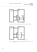
During test of the synchrocheck function for a single bay arrangement, these voltage inputs are
used:
12.2.1
At test of the synchrocheck function for a 1 1/2 CB diameter the following alternative voltage
inputs can be used for the three synchrocheck functions. The voltage is selected by activation of
different inputs in the voltage selection logic:
U-line
UL1, UL2 or UL3 voltage input on the terminal.
U-bus
U5 voltage input on the terminal
SYN1
U-line
UL1
Activate SYN1_FD1CLD
UL2
Activate SYN1_CB2CLD
U4
Activate SYN1_CB2CLD and CB3CLD
U-bus
U5
No activation of inputs necessary
SYN2
U-line
UL2
Activate SYN2_FD2CLD
U4
Activate SYN2_CB3CLD
U-bus
UL1
Activate SYN2_FD1CLD
Summary of Contents for REB 551-C3*2.5
Page 9: ...Contents ...
Page 21: ...12 Introduction to the installation and commissioning manual Chapter 1 Introduction ...
Page 27: ...18 Note signs Chapter 2 Safety information ...
Page 53: ...44 Installing the 56 64 kbit data communication cables Chapter 5 Installing the terminal ...
Page 59: ...50 Checking the binary I O circuits Chapter 6 Checking the external circuitry ...
Page 147: ...138 Repair support Chapter 16 Fault tracing and repair ...