84
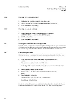
Preparing for test
Chapter 13
Verifying settings by secondary
injection
2
Preparing for test
2.1
Overview
This section describes how to prepare the terminal in order to verify settings.
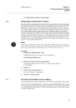
The preparation starts with making the connections to the test switch if included. This means
connecting the test equipment according to a valid terminal diagram for the specific REx 5xx
terminal. The terminal can then be set in test mode in order to facilitate the test of individual
functions and prevent unwanted operation from functions other than the tested. The test switch
should then be connected to the terminal. The user could also verify the connection and that the
analog inputs signals are measured correctly by injecting currents and voltages as required by
the specific REx 5xx terminal. The tested function should then be released. The disturbance re-
port settings could be checked to ensure that correct indications are given. The user could also
identify the function to test in the technical reference manual to retrieve signals and parameters
names etc.
2.2
Preparing the connection to the test equipment
The REx 5xx terminal can be equipped with a test switch of type RTXP 24. The test switch and
its associated test plug handle (RTXH 24) are a part of the COMBITEST system which gives a
secure and convenient testing of the terminal.
When the test-plug handle is inserted into the test switch, preparations for testing are automati-
cally carried out in the proper sequence (i.e. blocking of tripping circuits, short circuiting of
CT’s, opening of voltage circuits, making relay terminals available for secondary injection).
Terminals 1 and 12 of the test switch are not disconnected as they are used for dc supply of the
protection terminal.
The test-plug handle leads may be connected to any type of test equipment or instrument. When
a number of protection terminals of the same type are tested, the test-plug handle need be moved
only from the test switch of one protection terminal to the test switch of the other, without alter-
ing previously made connections.
To prevent unwanted tripping when the handle is withdrawn, latches on the handle secure it in
the half withdrawn position. In this position, all voltages and currents are restored to the protec-
tion terminal and any reenergizing transients are given a chance to decay before the trip circuits
are restored. When the latches are released, the handle can be completely withdrawn form the
test switch, restoring the trip circuits to the protection terminal.
If a test switch is not used necessary actions need to be taken according to circuit diagram.
Summary of Contents for REB 551-C3*2.5
Page 9: ...Contents ...
Page 21: ...12 Introduction to the installation and commissioning manual Chapter 1 Introduction ...
Page 27: ...18 Note signs Chapter 2 Safety information ...
Page 53: ...44 Installing the 56 64 kbit data communication cables Chapter 5 Installing the terminal ...
Page 59: ...50 Checking the binary I O circuits Chapter 6 Checking the external circuitry ...
Page 147: ...138 Repair support Chapter 16 Fault tracing and repair ...


