background image

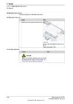
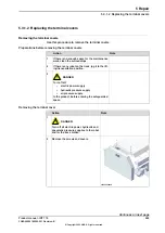
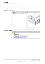
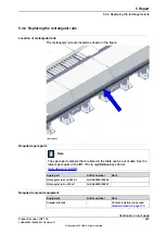
Refitting the track covers

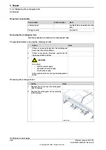
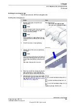
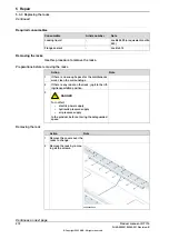
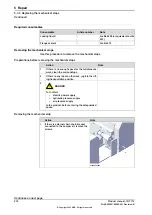
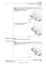
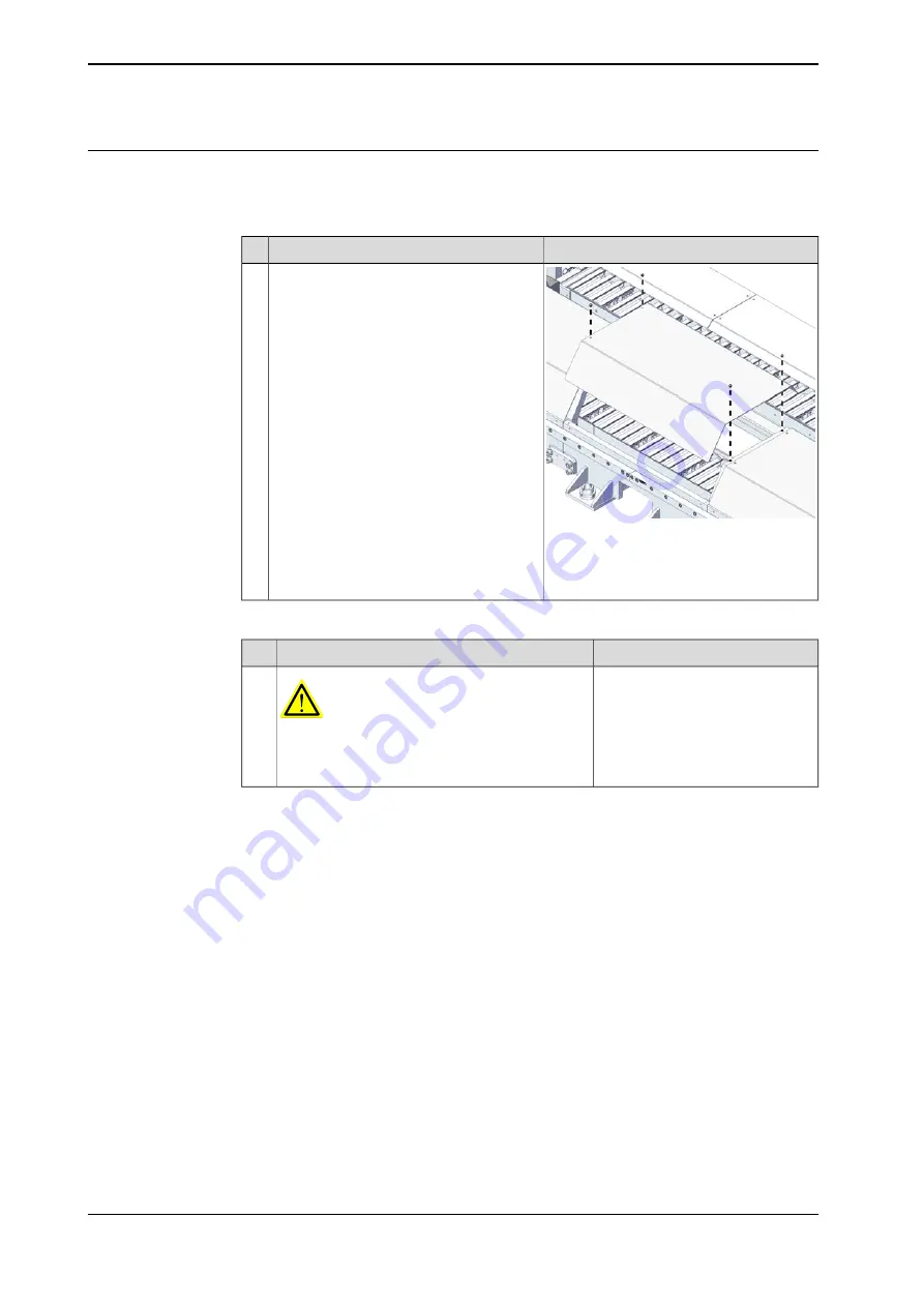
Use this procedure to refit the track cover.

Refitting the track cover

Note

Action

xx2200000616

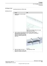
Refit the cover and secure with the screws.

1

Screws: ISO 7380-2 M6x12 Class 10.9 (4
pcs)
Tightening torque: 8 Nm

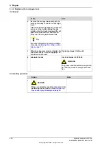
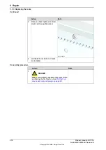
Concluding procedure

Note

Action

DANGER

Make sure all safety requirements are met when
performing the first test run. See

First test run

may cause injury or damage on page 29

.

1

262

Product manual - IRT 710

3HKA00000186299-001 Revision: B

© Copyright 2023 ABB. All rights reserved.

5 Repair

5.3.1.1 Replacing the track covers

Continued

Summary of Contents for IRT 710

Page 1: ...ROBOTICS Product manual IRT 710 ...

Page 2: ...Trace back information Workspace Systems version a40 Checked in 2023 10 18 Skribenta version 5 5 019 ...

Page 3: ...Product manual IRT 710 IRC5 Document ID 3HKA00000186299 001 Revision B Copyright 2023 ABB All rights reserved Specifications subject to change without notice ...

Page 4: ...ranty by ABB for losses damage to persons or property fitness for a specific purpose or the like In no event shall ABB be liable for incidental or consequential damages arising from use of this manual and products described herein This manual and parts thereof must not be reproduced or copied without ABB s written permission Keep for future reference Additional copies of this manual may be obtaine...

Page 5: ...Safety signals and symbols 39 1 4 1 Safety signals in the manual 40 1 4 2 Safety symbols on product labels 46 1 5 Product stopping functions 48 1 6 Safety during installation and commissioning 50 1 7 Safety during operation 52 1 8 Safety during maintenance and repair 52 1 8 1 Safety during maintenance and repair 55 1 8 2 Emergency release of the Product axes 56 1 9 Safety during troubleshooting 57...

Page 6: ...onal 178 3 8 Zone division 179 4 Maintenance 179 4 1 Introduction 180 4 2 Maintenance schedule and expected component life 180 4 2 1 Specification of maintenance intervals 181 4 2 2 Maintenance schedule 183 4 2 3 Expected component life 184 4 3 Inspection activities 184 4 3 1 Inspecting the information labels 186 4 3 2 Inspecting the lubrication system 188 4 3 3 Inspecting the cable chain 190 4 3 ...

Page 7: ...able chain 335 6 Calibration 335 6 1 Introduction to calibration 335 6 1 1 Introduction and calibration terminology 336 6 1 2 Calibration methods 337 6 1 3 When to calibrate 338 6 2 Synchronization marks and track motion movement directions 338 6 2 1 Synchronization marks and synchronization position for track motions 342 6 3 Updating revolution counters 342 6 3 1 Updating revolution counters for ...

Page 8: ...nd lifting instructions 377 9 Spare parts 377 9 1 Spare part lists and illustrations 379 10 Circuit diagrams 381 Index 8 Product manual IRT 710 3HKA00000186299 001 Revision B Copyright 2023 ABB All rights reserved Table of contents ...

Page 9: ...foundation to making it ready for operation maintenance work repair work decommissioning work Note It is the responsibility of the integrator to conduct a risk assessment of the final application It is the responsibility of the integrator to provide safety and user guides for the robot system Who should read this manual This manual is intended for installation personnel maintenance personnel repai...

Page 10: ...044270 001 IRB 6700 product manual 3HAC039838 001 IRB 760 product manual 3HAC025755 001 IRB 660 product manual 3HAC033453 001 IRB 4600 product manual 3HAC022032 001 IRB 4400 product manual 3HAC039842 001 IRB 460 product manual Revisions Description Revision First edition A The following updates are done in this revision Minor corrections Updated content with new drive unit bracket and backlash too...

Page 11: ...ion Troubleshooting Decommissioning Reference information safety standards unit conversions screw joints lists of tools Spare parts list with corresponding figures or references to separate spare parts lists References to circuit diagrams Technical reference manuals The technical reference manuals describe reference information for robotics products for example lubrication the RAPID language and s...

Page 12: ...ndling of the products The manuals are aimed at those having first hand operational contact with the product that is production cell operators programmers and troubleshooters 12 Product manual IRT 710 3HKA00000186299 001 Revision B Copyright 2023 ABB All rights reserved Product documentation Continued ...

Page 13: ... include specific safety information when dangerous steps are to be performed Read more in the chapter Safety on page 15 Illustrations The product is illustrated with general figures that does not take painting or protection type in consideration Likewise certain work methods or general information that is valid for several product models can be illustrated with illustrations that show a different...

Page 14: ...This page is intentionally left blank ...

Page 15: ...pairs carried out by in experienced or non qualified personnel Foreign objects Force majeure Nation region specific regulations To protect personnel the complete system must be designed and installed in accordance with the safety requirements set forth in the standards and regulations of the country where the Product is installed To be observed by the supplier of the complete system The integrator...

Page 16: ...king or malfunctioning rotating tool or other device fitted to the Product Safe handling Users shall not be exposed to hazards including slipping tripping and falling hazards It must be possible to safely turn off tools such as milling cutters etc Make sure that guards remain closed until the cutters stop rotating It should be possible to release parts by manual operation valves Safe design Emerge...

Page 17: ...uence of alcohol drugs or any other intoxicating substances are not allowed to install maintain service repair or use the robot The plant liable must make sure that the personnel is trained on the robot and on responding to emergency or abnormal situations Personal protective equipment Use personal protective equipment as stated in the instructions Product manual IRT 710 17 3HKA00000186299 001 Rev...

Page 18: ...ction capability d 40 mm When the detection diameter of the sensor d 40 mm it cannot detect the intrusion of the hand but can only detect the body The calculation formula corresponding to the minimum safety distance is S K T C K 2000 mm s Approaching speed of the walking human T The maximum time for the machine to stop Light curtain response time C 850 mm Traverse distance d Light curtain detectio...

Page 19: ... human T The maximum time for the machine to stop Interlock response time C 850 mm Traverse distance Note If the recalculated value 500mm then S should be set as 500 mm Note The interlock device should follow the dual channel requirements Continues on next page Product manual IRT 710 19 3HKA00000186299 001 Revision B Copyright 2023 ABB All rights reserved 1 Safety 1 1 3 Safeguarded space Continued...

Page 20: ... regular openings Persons of 14 years of age and above Safety distance sr Opening Illustration Part of body Round Square Slot 2 2 2 e 4 xx2200000857 Fingertip 5 5 10 4 e 6 5 15 20 6 e 8 xx2200000858 Finger up to knuckle joint 20 25 80 8 e 10 80 80 100 10 e 12 xx2200000859 Hand 120 120 120 12 e 20 120 120 850i 20 e 30 120 200 850 30 e 40 xx2200000860 Arm up to junction with shoulder 850 850 850 40 ...

Page 21: ...the opening between the ground and the bottom of the fence should no exceed 180 mm Product manual IRT 710 21 3HKA00000186299 001 Revision B Copyright 2023 ABB All rights reserved 1 Safety 1 1 3 Safeguarded space Continued ...

Page 22: ...ve equipment Note Always wear non slip safety shoes for any commissioning maintenance repair procedure 22 Product manual IRT 710 3HKA00000186299 001 Revision B Copyright 2023 ABB All rights reserved 1 Safety 1 2 1 Personal protective equipment ...

Page 23: ... Note Use a CARBON DIOXIDE CO2 extinguisher in the event of a fire in the Product or controller Product manual IRT 710 23 3HKA00000186299 001 Revision B Copyright 2023 ABB All rights reserved 1 Safety 1 2 2 Fire extinguishing ...

Page 24: ...sing the brakes make sure that the weight of any part of the Product does not increase the pressure on the trapped person further increasing any injury DANGER When releasing the holding brakes the Product parts may move very quickly and sometimes in unexpected ways Make sure no personnel is near or beneath the Product 24 Product manual IRT 710 3HKA00000186299 001 Revision B Copyright 2023 ABB All ...

Page 25: ...troller before proceeding work Note Switch off all main power switches in a MultiMove system Spot welding cabinet Wait for 5 minutes to let the capacitors discharge after the power has been switched off DANGER Even if the main switch is switched off the capacitors can cause electric shock if not given the time to discharge Product manual IRT 710 25 3HKA00000186299 001 Revision B Copyright 2023 ABB...

Page 26: ...afety lock Make sure that no one else can turn on the power to the controller and Product while you are working with the system A good method is to remove the power cable to the controller If the Product is installed at a height hanging or other than standing directly on the floor there may be additional risks than those for a Product standing directly on the floor Energy stored in the Product for...

Page 27: ...odifications to the Product Connection of external safety devices Apart from the built in safety functions the Product is also supplied with an interface for the connection of external safety devices An external safety function can interact with other machines and peripheral equipment via this interface This means that control signals can act on safety signals received from the peripheral equipmen...

Page 28: ...gency stop equipment is cor rectly installed and connected 1 How to use the hold to run function is de scribed in section How to use the hold to run function in the Operating manual IRC5 with FlexPendant Usually the hold to run function is active only in manual full speed mode To in crease safety it is also possible to activate hold to run for manual reduced speed with a system parameter 2 The hol...

Page 29: ...ety equipment installed to secure the position or restrict the Product motion during service activity is removed 3 Verify that the fixture and work piece are well secured if applicable 4 Install all safety equipment properly 5 Make sure all personnel are standing at a safe distance from the Product and is out of its reach behind safety fences or similar 6 Verify that all required covers or padding...

Page 30: ...devices mounted on the Product or inside the cell Keep away from rotating and moving parts to not get entangled with hair or clothing Keep clear of moving parts so that limbs hands or fingers do not get trapped or crushed by the Product To prevent anyone else from taking control of the Product always put a safety lock on the cell door and bring the three position enabling device with you when ente...

Page 31: ...Product switches to the MOTORS OFF state To ensure safe use of the teach pendant the following must be implemented The enabling device must never be rendered inoperational in any way During programming and testing the enabling device must be released as soon as there is no need for the Product to move Anyone entering the working space of the Product must always hold the teach pendant This is to pr...

Page 32: ...aranteed if the valid regulations are followed Voltage related risks IRC5 controller A danger of high voltage is associated with for example the following parts Be aware of stored electrical energy DC link Ultracapacitor bank unit in the controller Units such as I O modules can be supplied with power from an external source The main supply main switch The transformers The power unit The control po...

Page 33: ...e live even if the Product system is in the OFF position Power supply cables which are in motion during the working process may be damaged Product manual IRT 710 33 3HKA00000186299 001 Revision B Copyright 2023 ABB All rights reserved 1 Safety 1 3 6 Risks associated with live electric parts Continued ...

Page 34: ... your hand at some distance to feel if heat is radiating from the potentially hot component before actually touching it Wait until the potentially hot component has cooled if it is to be removed or handled in any other way Do not put anything on hot metal surfaces e g paper or plastic 34 Product manual IRT 710 3HKA00000186299 001 Revision B Copyright 2023 ABB All rights reserved 1 Safety 1 3 7 Hot...

Page 35: ...the MOTORS OFF 3 Try to move the carriage manually 4 Inspect and verify that the axis maintains its position If the manipulator does not change position as the motors are switched off then the brake function is adequate Note It is recommended to run the service routine BrakeCheck as part of the regular maintenance see the operating manual for the robot controller For Products with the option SafeM...

Page 36: ...losion fire may follow depending upon the circumstances Note Appropriate disposal regulations must be observed Safe handling Use safety glasses when handling the batteries In the event of leakage wear rubber gloves and chemical apron In the event of fire use self contained breathing apparatus Do not short circuit recharge puncture incinerate crush immerse force discharge or expose to temperatures ...

Page 37: ...tion Action Description Warning Make sure that protective gear like goggles and gloves are al ways worn during this activity Changing and draining gearbox oil or grease may require hand ling hot lubricant heated up to 90 C Hot oil or grease Make sure that protective gear like goggles and gloves are al ways worn When working with gearbox lub ricant there is a risk of an allergic reaction Allergic r...

Page 38: ... the total volume of the gearbox When changing the lubricant the amount refilled may differ from the specified amount depending on how much has previously been drained from the gearbox Specified amount de pends on drained volume When draining the oil make sure that as much oil as possible is drained from the gearbox The reason for this is to drain as much oil sludge and metal chips as possible fro...

Page 39: ... ous situation which if not avoided will result in ser ious injury DANGER Signal word used to indicate a potentially hazardous situation which if not avoided could result in serious injury WARNING Signal word used to indicate a potentially hazardous situation related to electrical hazards which if not avoided could result in serious injury ELECTRICAL SHOCK Signal word used to indicate a potentiall...

Page 40: ...lish German and French Symbols on safety labels Description Symbol Warning xx0900000812 Warns that an accident may occur if the instructions are not followed that can lead to serious injury possibly fatal and or great damage to the product It applies to warnings that apply to danger with for example contact with high voltage electrical units explosion or fire risk risk of poisonous gases risk of c...

Page 41: ...ot disassemble xx0900000815 Disassembling this part can cause injury Extended rotation xx0900000814 This axis has extended rotation working area compared to standard Brake release xx0900000808 Pressing this button will release the brakes This means that the parts of the Product can fall down Continues on next page Product manual IRT 710 41 3HKA00000186299 001 Revision B Copyright 2023 ABB All righ...

Page 42: ...e burns Both signs are used 3HAC 4431 1 06 xx1300001087 Brake release buttons xx0900000820 xx1000001140 Lifting bolt xx0900000821 Continues on next page 42 Product manual IRT 710 3HKA00000186299 001 Revision B Copyright 2023 ABB All rights reserved 1 Safety 1 4 2 Safety symbols on product labels Continued ...

Page 43: ...ed energy xx0900000825 Warns that this part contains stored energy Used in combination with Do not disassemble symbol Pressure xx0900000826 Warns that this part is pressurized Usually contains additional text with the pressure level Continues on next page Product manual IRT 710 43 3HKA00000186299 001 Revision B Copyright 2023 ABB All rights reserved 1 Safety 1 4 2 Safety symbols on product labels ...

Page 44: ...n these parts can cause damage to the parts Must wear safety helmet xx1800002608 Must wear non slip safety shoes 板䦃收㷕 暏 1YWX IEV RSR WPMT WEJIX WLSIW xx2200001149 Continues on next page 44 Product manual IRT 710 3HKA00000186299 001 Revision B Copyright 2023 ABB All rights reserved 1 Safety 1 4 2 Safety symbols on product labels Continued ...

Page 45: ...x1800002609 Warns that entering the working areas can cause injuries or damages Product manual IRT 710 45 3HKA00000186299 001 Revision B Copyright 2023 ABB All rights reserved 1 Safety 1 4 2 Safety symbols on product labels Continued ...

Page 46: ...ller For more information see Product manual IRC5 After emergency stop triggered Check the rectangular rail where the robot stopped for no step while passing the rectangular rail junction xx2200001185 Continues on next page 46 Product manual IRT 710 3HKA00000186299 001 Revision B Copyright 2023 ABB All rights reserved 1 Safety 1 5 Product stopping functions ...

Page 47: ... gap between the rectangular rail and section xx2200001192 Product manual IRT 710 47 3HKA00000186299 001 Revision B Copyright 2023 ABB All rights reserved 1 Safety 1 5 Product stopping functions Continued ...

Page 48: ...the robot system for example that guards remain active until identified hazards are reduced to an acceptable level Allergenic material See Environmental information on page361 for specification of allergenic materials in the product if any Securing the robot to the foundation The robot must be properly fixed to its foundation support as described in the respective product manual When the robot is ...

Page 49: ...cked in accordance with applicable standards Other hazards The product may perform unexpected limited movement WARNING Product movements can cause serious injuries on users and may damage equipment The risk assessment should also consider other hazards arising from the application such as but not limited to Water Compressed air Hydraulics End effector hazards require particular attention for appli...

Page 50: ...omatic and initiating automatic operation Unexpected movement of product WARNING Hazards due to the use of brake release devices and or gravity beneath the manipulator shall be considered Continues on next page 50 Product manual IRT 710 3HKA00000186299 001 Revision B Copyright 2023 ABB All rights reserved 1 Safety 1 7 Safety during operation ...

Page 51: ...ed horizontally or vertically during high speed movement This may lead to unexpected hazards xx2200001196 xx2200001197 Product manual IRT 710 51 3HKA00000186299 001 Revision B Copyright 2023 ABB All rights reserved 1 Safety 1 7 Safety during operation Continued ...

Page 52: ...ns are working as intended Hot surfaces Surfaces can be hot after running the Product and touching these may result in burns Allow the surfaces to cool down before maintenance or repair Allergic reaction Elimination Action Description Warning Make sure that protective gear like goggles and gloves are al ways worn When working with lubricants there is a risk of an allergic reac tion Allergic reacti...

Page 53: ...y been drained from the gearbox Specified amount de pends on drained volume For lifetime reasons always drain as much oil as possible from the gearbox The magnetic oil plugs will gather residual metal chips Contaminated oil in gearboxes Hazards related to batteries Under rated conditions the electrode materials and liquid electrolyte in the batteries are sealed and not exposed to the outside There...

Page 54: ...ravity beneath the manipulator shall be considered Related information See also the safety information related to installation and operation 54 Product manual IRT 710 3HKA00000186299 001 Revision B Copyright 2023 ABB All rights reserved 1 Safety 1 8 1 Safety during maintenance and repair Continued ...

Page 55: ... the rail Increased injury Before releasing the brakes make sure that the weight of the carriage does not result in additional hazards for example even more severe injuries on a trapped person DANGER When releasing the holding brakes the Product axes may move very quickly and sometimes in unexpected ways Make sure no personnel is near or beneath the robot Product manual IRT 710 55 3HKA00000186299 ...

Page 56: ...gineers A risk assessment must be done to address both product and robot system specific hazards WARNING Hazards due to the use of brake release devices and or gravity beneath the manipulator shall be considered Product may perform unexpected limited movement WARNING Manipulator movements can cause serious injuries on users and may damage equipment Related information See also the safety informati...

Page 57: ...Unexpected movement of product WARNING Hazards due to the use of brake release devices and or gravity beneath the manipulator shall be considered Product manual IRT 710 57 3HKA00000186299 001 Revision B Copyright 2023 ABB All rights reserved 1 Safety 1 10 Safety during decommissioning ...

Page 58: ...This page is intentionally left blank ...

Page 59: ...robably needs to be additional space at the ends of the track motion at the installation site Add space as required Formula for carriage tracks Required space for carriage tracks is determined with the following formula Required space mm 1000 x N1 2 x 66 5002 Dimensions Without external cable chain 1000 a 980 xx2200001281 1 Value of N is equal to the number of sections 2 Valid if the length is N 0...

Page 60: ...Requirement Flat foundations give better repeatability of the resolver calibration compared to original settings on delivery from ABB 1 mm m movement direction 0 5 mm m Perpendic ular to movement dir ection Flatness of foundation surface The value for levelness aims at the circum stance of the anchoring points in the robot base Overall height differ ence 10 mm Mechanical stops There are no adjusta...

Page 61: ...a pipes and etc Tip There are three types carriages used in IRT 710 For more information see IRT 710 carriage overview on page 93 The following table takes the large robot carriage weight into count If any robot carriage or transfer carriage is used please minus the corresponding weight For more information on the carriages weight see Weight Carriages on page93 4 Carriages 3 Carriages 2 Carriages ...

Page 62: ...3 5 7689 7067 6537 5849 5915 5270 14 7797 7184 6645 5957 6023 5378 14 5 8063 7450 6917 6186 6289 5601 15 8183 7558 7025 6294 6397 5709 15 5 8449 7824 7291 6517 6666 5935 16 8557 7941 7399 6625 6774 6043 16 5 8823 8207 7671 6854 7040 6266 17 8943 8315 7779 6962 7148 6374 17 5 9209 8581 8045 7185 7417 6600 18 9317 8698 8153 7293 7525 6708 18 5 9583 8964 8425 7522 7791 6931 19 9703 9072 8533 7630 789...

Page 63: ...57 11638 12405 11029 31 5 14529 13880 13323 11861 12674 11255 32 14637 13997 13431 11969 12782 11363 32 5 14903 14263 13703 12198 13048 11586 33 15023 14371 13811 12306 13156 11694 33 5 15289 14637 14077 12529 13425 11920 34 15397 14754 14185 12637 13533 12028 34 5 15663 15020 14457 12866 13799 12251 35 15783 15128 14565 12974 13907 12359 35 5 16049 15394 14831 13197 14176 12585 36 16157 15511 149...

Page 64: ... C Minimum ambient temperature 45 C Maximum ambient temperature 70 C Maximum ambient temperature less than 24 hrs Maximum 95 at constant temper ature Maximum ambient humidity 1 000 m Maximum ambient altitude Operating conditions The table shows the allowed operating conditions for the robot Value Parameter 5 Ci 41 F Minimum ambient temperature 45 C 113 F Maximum ambient temperature Maximum 95 at c...

Page 65: ...t A power consumption measurement of a track motion with manipulator could be done with a simulated cycle in RobotStu dio See Operating manual RobotStudio Product manual IRT 710 65 3HKA00000186299 001 Revision B Copyright 2023 ABB All rights reserved 2 Technical data 2 1 Technical data Continued ...

Page 66: ...506 2197 309 Mirrored 4 3006 2697 309 Standard 4 5 3506 3197 309 Standard 5 3506 3197 309 Mirrored 5 4006 3697 309 Standard 5 5 4506 4197 309 Standard 6 4506 4197 309 Mirrored 6 5006 4697 309 Standard 6 5 5506 5197 309 Standard 7 5506 5197 309 Mirrored 7 6006 5697 309 Standard 7 5 6506 6197 309 Standard 8 6506 6197 309 Mirrored 8 7006 6697 309 Standard 8 5 7506 7197 309 Standard 9 7506 7197 309 Mi...

Page 67: ... 309 Standard 14 5 13506 13197 309 Standard 15 13506 13197 309 Mirrored 15 14006 13697 309 Standard 15 5 14506 14197 309 Standard 16 14506 14197 309 Mirrored 16 15006 14697 309 Standard 16 5 15506 15197 309 Standard 17 15506 15197 309 Mirrored 17 16006 15697 309 Standard 17 5 16506 16197 309 Standard 18 16506 16197 309 Mirrored 18 17006 16697 309 Standard 18 5 17506 17197 309 Standard 19 17506 171...

Page 68: ...6 24197 309 Mirrored 26 25006 24697 309 Standard 26 5 25506 25197 309 Standard 27 25506 25197 309 Mirrored 27 26006 25697 309 Standard 27 5 26506 26197 309 Standard 28 26506 26197 309 Mirrored 28 27006 26697 309 Standard 28 5 27506 27197 309 Standard 29 27506 27197 309 Mirrored 29 28006 27697 309 Standard 29 5 28506 28197 309 Standard 30 28506 28197 309 Mirrored 30 29006 28697 309 Standard 30 5 29...

Page 69: ...Standard 36 5 35506 35197 309 Standard 37 35506 35197 309 Mirrored 37 36006 35697 309 Standard 37 5 36506 36197 309 Standard 38 36506 36197 309 Mirrored 38 37006 36697 309 Standard 38 5 37506 37197 309 Standard 39 37506 37197 309 Mirrored 39 38006 37697 309 Standard 39 5 38506 38197 309 Standard 40 38506 38197 309 Mirrored 40 39006 38697 309 Standard 40 5 Double carriages Please check the layout o...

Page 70: ...9 Standard 3927 309 Standard 7 4236 3927 309 Mirrored 3927 309 Standard 7 4236 3927 309 Mirrored 197 4039 Mirrored 7 4736 197 4539 Standard 4427 309 Standard 7 5 5236 197 5039 Standard 4927 309 Standard 8 5236 4927 309 Mirrored 4927 309 Standard 8 5236 4927 309 Mirrored 197 5039 Mirrored 8 5736 197 5539 Standard 5427 309 Standard 8 5 6236 197 6039 Standard 5927 309 Standard 9 6236 5927 309 Mirrore...

Page 71: ...9 Standard 15 12236 11927 309 Mirrored 197 12039 Mirrored 15 12736 197 12539 Standard 12427 309 Standard 15 5 13236 197 13039 Standard 12927 309 Standard 16 13236 12927 309 Mirrored 12927 309 Standard 16 13236 12927 309 Mirrored 197 13039 Mirrored 16 13736 197 13539 Standard 13427 309 Standard 16 5 14236 197 14039 Standard 13927 309 Standard 17 14236 13927 309 Mirrored 13927 309 Standard 17 14236 ...

Page 72: ...rd 20927 309 Standard 24 21236 20927 309 Mirrored 20927 309 Standard 24 21236 20927 309 Mirrored 197 21039 Mirrored 24 21736 197 21539 Standard 21427 309 Standard 24 5 22236 197 22039 Standard 21927 309 Standard 25 22236 21927 309 Mirrored 21927 309 Standard 25 22236 21927 309 Mirrored 197 22039 Mirrored 25 22736 197 22539 Standard 22427 309 Standard 25 5 23236 197 23039 Standard 22927 309 Standar...

Page 73: ...d 29427 309 Standard 32 5 30236 197 30039 Standard 29927 309 Standard 33 30236 29927 309 Mirrored 29927 309 Standard 33 30236 29927 309 Mirrored 197 30039 Mirrored 33 30736 197 30539 Standard 30427 309 Standard 33 5 31236 197 31039 Standard 30927 309 Standard 34 31236 30927 309 Mirrored 30927 309 Standard 34 31236 30927 309 Mirrored 197 31039 Mirrored 34 31736 197 31539 Standard 31427 309 Standard...

Page 74: ...5927 309 Mirrored 35927 309 Standard 39 36236 35927 309 Mirrored 197 36039 Mirrored 39 36736 197 36539 Standard 36427 309 Standard 39 5 37236 197 37039 Standard 36927 309 Standard 40 37236 36927 309 Mirrored 36927 309 Standard 40 37236 36927 309 Mirrored 197 37039 Mirrored 40 37736 197 37539 Standard 37427 309 Standard 40 5 Three carriages Please check the layout of work range attached file and di...

Page 75: ...ndard 11 6966 927 6039 Standard 6657 309 Standard 197 6769 Standard 11 7466 6427 1039 Standard 197 7269 Standard 7157 309 Standard 11 5 7966 6927 1039 Standard 197 7769 Standard 7657 309 Standard 12 7966 927 7039 Standard 7657 309 Standard 197 7769 Standard 12 8466 7427 1039 Standard 197 8269 Standard 8157 309 Standard 12 5 8966 7927 1039 Standard 197 8769 Standard 8657 309 Standard 13 8966 927 80...

Page 76: ...rd 18157 309 Standard 22 5 18966 17927 1039 Standard 197 18769 Standard 18657 309 Standard 23 18966 927 18039 Standard 18657 309 Standard 197 18769 Standard 23 19466 18427 1039 Standard 197 19269 Standard 19157 309 Standard 23 5 19966 18927 1039 Standard 197 19769 Standard 19657 309 Standard 24 19966 927 19039 Standard 19657 309 Standard 197 19769 Standard 24 20466 19427 1039 Standard 197 20269 St...

Page 77: ...rd 197 29769 Standard 34 30466 29427 1039 Standard 197 30269 Standard 30157 309 Standard 34 5 30966 29927 1039 Standard 197 30769 Standard 30657 309 Standard 35 30966 927 30039 Standard 30657 309 Standard 197 30769 Standard 35 31466 30427 1039 Standard 197 31269 Standard 31157 309 Standard 35 5 31966 30927 1039 Standard 197 31769 Standard 31657 309 Standard 36 31966 927 31039 Standard 31657 309 St...

Page 78: ...tached file and dimension information xx2200000404 Description Pos 813 mm A 1270 mm B minim um Stroke C Continues on next page 78 Product manual IRT 710 3HKA00000186299 001 Revision B Copyright 2023 ABB All rights reserved 2 Technical data 2 2 Working range ...

Page 79: ...d 13 7696 6657 1039 Mirrored 927 6769 Mirrored 7387 309 Mirrored 197 7499 Mirrored 13 8196 927 7269 Standard 7157 1039 Standard 197 7999 Standard 7887 309 Standard 13 5 8696 927 7769 Standard 7657 1039 Standard 197 8499 Standard 8387 309 Standard 14 8696 7657 1039 Mirrored 927 7769 Mirrored 8387 309 Mirrored 197 8499 Mirrored 14 9196 927 8269 Standard 8157 1039 Standard 197 8999 Standard 8887 309 ...

Page 80: ...ard 18887 309 Standard 24 5 19696 927 18769 Standard 18657 1039 Standard 197 19499 Standard 19387 309 Standard 25 19696 18657 1039 Mirrored 927 18769 Mirrored 19387 309 Mirrored 197 19499 Mirrored 25 20196 927 19269 Standard 19157 1039 Standard 197 19999 Standard 19887 309 Standard 25 5 20696 927 19769 Standard 19657 1039 Standard 197 20499 Standard 20387 309 Standard 26 20696 19657 1039 Mirrored ...

Page 81: ...red 197 29499 Mirrored 35 30196 927 29269 Standard 29157 1039 Standard 197 29999 Standard 29887 309 Standard 35 5 30696 927 29769 Standard 29657 1039 Standard 197 30499 Standard 30387 309 Standard 36 30696 29657 1039 Mirrored 927 29769 Mirrored 30387 309 Mirrored 197 30499 Mirrored 36 31196 927 30269 Standard 30157 1039 Standard 197 30999 Standard 30887 309 Standard 36 5 31696 927 30769 Standard 3...

Page 82: ...ion Item ABB Logo 1 Rating Label 2 Lifting Label 3 NO SHOCK Warning Label 4 Instruction Plate 5 Electric shock Warning Label 6 High Temperature Warning Label 7 82 Product manual IRT 710 3HKA00000186299 001 Revision B Copyright 2023 ABB All rights reserved 2 Technical data 2 3 Information labels ...

Page 83: ...ing part of the IRT 710 The top plate receives the tooling robot Carriage The static part of the IRT 710 Track The track is delivered as modules to be assembled by the cus tomer as described in Assembling the track motion IRT 710 on page 120 Maximum stroke of the carriage Travel length The Serial Measurement Board Box a control box which in cludes the SMB card for the IRT 710 axis as well as the r...

Page 84: ...This page is intentionally left blank ...

Page 85: ...s commenced all safety information must be observed There are general safety aspects that must be read through as well as more specific safety information that describes the danger and safety risks when performing the procedures Read the chapter Safety on page15 before performing any installation work Note Always connect the IRT 710 and the robot to protective earth and residual current device RCD...

Page 86: ... of the track motion 2 Lifting track motion using lifting slings Lift the track motion 3 Assembling the track motion IRT 710 on page 120 Assemble the track motion 4 Assembling the pedestal option on page 139 Assembling the pedestal option 5 Assembly of the manipulator on page 141 Assemble the manipulator 6 Electrical installation on page 143 Electrical installation 7 Software installation on page ...

Page 87: ... Note Do not clean any of the pre lubricated parts of the track motion IRT 710 5 Make sure that the lifting accessory used if required is suitable to handle the weight of the product as specified in Weight robot on page 61 6 If the product is not installed directly it must be stored as described in Storage con ditions on page 64 7 Make sure that the expected operating environment of the product co...

Page 88: ... 24 5 3 4 6 6 5 6 6 3 4 6 6 5 6 6 3 4 6 6 5 6 6 3 4 6 6 5 6 6 25 25 5 4 4 6 6 5 6 6 4 4 6 6 5 6 6 4 4 6 6 5 6 6 4 4 6 6 5 6 6 26 26 5 4 5 6 6 5 6 6 4 5 6 6 5 6 6 4 5 6 6 5 6 6 4 5 6 6 5 6 6 27 27 5 5 5 6 6 5 6 6 5 5 6 6 5 6 6 5 5 6 6 5 6 6 5 5 6 6 5 6 6 28 28 5 5 6 6 6 5 6 6 5 6 6 6 5 6 6 5 6 6 6 5 6 6 5 6 6 6 5 6 6 29 29 5 6 6 6 6 5 6 6 6 6 6 6 5 6 6 6 6 6 6 5 6 6 6 6 6 6 5 6 6 30 30 5 3 6 6 6 6 ...

Page 89: ...entification plate and compare it to the delivery note The identification plates are shown in the figure R T 1 2 3 4 3 3 5 4 40 Carriage type Carriage number Length Variant IRT 710 XX X xx2200000408 R represents Robot T represents Transfer Product manual IRT 710 89 3HKA00000186299 001 Revision B Copyright 2023 ABB All rights reserved 3 Installation and commissioning 3 3 2 Acceptance inspection ...

Page 90: ...rapping in place and the strapping plates attached to the chains the chain can only be folded in half The chain can either be folded so that the chain is lying on itself or laid on its side xx1300000884 Continues on next page 90 Product manual IRT 710 3HKA00000186299 001 Revision B Copyright 2023 ABB All rights reserved 3 Installation and commissioning 3 3 3 1 Storing the cable chain ...

Page 91: ...ace and the strapping plate not connected to the chain the chain can be rolled up and stored lying on its side xx1300000885 Product manual IRT 710 91 3HKA00000186299 001 Revision B Copyright 2023 ABB All rights reserved 3 Installation and commissioning 3 3 3 1 Storing the cable chain Continued ...

Page 92: ...r bracket E Track cover F Terminal cover G External cable chain cover H External cable chain J Rack cover K Rack L The same components are used in different layout variants Continues on next page 92 Product manual IRT 710 3HKA00000186299 001 Revision B Copyright 2023 ABB All rights reserved 3 Installation and commissioning 3 4 1 Track motion IRT 710 overview ...

Page 93: ...wer F Lubrication system G Weight Carriages Transfer carriage Medium robot car riage Large robot carriage Carriage type 537 kg 517 kg 556 kg Weight Continues on next page Product manual IRT 710 93 3HKA00000186299 001 Revision B Copyright 2023 ABB All rights reserved 3 Installation and commissioning 3 4 1 Track motion IRT 710 overview Continued ...

Page 94: ... plate is used for IRB 7600 760 6700 6660 6650S 6620 660 and 460 xx2200000605 90 per step xx2200000606 45 per step Continues on next page 94 Product manual IRT 710 3HKA00000186299 001 Revision B Copyright 2023 ABB All rights reserved 3 Installation and commissioning 3 4 1 Track motion IRT 710 overview Continued ...

Page 95: ...g plate is used for IRB 4600 and 4400 xx2200000607 90 per step xx2200000608 45 per step Continues on next page Product manual IRT 710 95 3HKA00000186299 001 Revision B Copyright 2023 ABB All rights reserved 3 Installation and commissioning 3 4 1 Track motion IRT 710 overview Continued ...

Page 96: ... the dimensions in mm xx2200000609 Easily damaged parts on the track motion Do not step on the locations marked in the figure since they are easily damaged xx2200000644 96 Product manual IRT 710 3HKA00000186299 001 Revision B Copyright 2023 ABB All rights reserved 3 Installation and commissioning 3 4 1 Track motion IRT 710 overview Continued ...

Page 97: ...ne carriage xx2200000610 Two carriages xx2200000611 Three carriages xx2200000612 Four carriages xx2200000613 Continues on next page Product manual IRT 710 97 3HKA00000186299 001 Revision B Copyright 2023 ABB All rights reserved 3 Installation and commissioning 3 4 2 Track motion IRT 710 layout ...

Page 98: ...rd mounting xx2200001151 Mirrored mounting xx2200001152 98 Product manual IRT 710 3HKA00000186299 001 Revision B Copyright 2023 ABB All rights reserved 3 Installation and commissioning 3 4 2 Track motion IRT 710 layout Continued ...

Page 99: ...ccording to the tables in Lifting zones on page 99 Lifting position on page 100 and Lifting weight on page 108 Required equipment Note Article number Equipment Overhead crane 5 000 kg capacity Lifting chain including two short belts lifting belt Lifting zones Max 60 xx2200000645 WARNING Never place lifting straps wider than a combined angle of max 60 Continues on next page Product manual IRT 710 9...

Page 100: ... should be placed Carriage and lifting position Length m Car riage No xx2200000406 6 5 3 xx2200000407 6 Continues on next page 100 Product manual IRT 710 3HKA00000186299 001 Revision B Copyright 2023 ABB All rights reserved 3 Installation and commissioning 3 4 3 1 Lifting and moving track motion IRT 710 Continued ...

Page 101: ...0647 6 xx2200000648 5 5 xx2200000649 5 xx2200000650 4 5 xx2200000651 4 Continues on next page Product manual IRT 710 101 3HKA00000186299 001 Revision B Copyright 2023 ABB All rights reserved 3 Installation and commissioning 3 4 3 1 Lifting and moving track motion IRT 710 Continued ...

Page 102: ...200000654 5 5 xx2200000655 5 xx2200000656 4 5 xx2200000657 4 xx2200000658 3 5 3 Continues on next page 102 Product manual IRT 710 3HKA00000186299 001 Revision B Copyright 2023 ABB All rights reserved 3 Installation and commissioning 3 4 3 1 Lifting and moving track motion IRT 710 Continued ...

Page 103: ...oceed as follows to lift the track motion IRT 710 using the fork lift xx2200000789 Continues on next page Product manual IRT 710 103 3HKA00000186299 001 Revision B Copyright 2023 ABB All rights reserved 3 Installation and commissioning 3 4 3 1 Lifting and moving track motion IRT 710 Continued ...

Page 104: ...ack motion IRT 710 using an overhead crane xx2200000790 Continues on next page 104 Product manual IRT 710 3HKA00000186299 001 Revision B Copyright 2023 ABB All rights reserved 3 Installation and commissioning 3 4 3 1 Lifting and moving track motion IRT 710 Continued ...

Page 105: ...round plates Depending on the lenght of the track motion the number of roller dollies varies See table for information xx2200000660 Continues on next page Product manual IRT 710 105 3HKA00000186299 001 Revision B Copyright 2023 ABB All rights reserved 3 Installation and commissioning 3 4 3 1 Lifting and moving track motion IRT 710 Continued ...

Page 106: ... is shown in the following illustration and table Continues on next page 106 Product manual IRT 710 3HKA00000186299 001 Revision B Copyright 2023 ABB All rights reserved 3 Installation and commissioning 3 4 3 1 Lifting and moving track motion IRT 710 Continued ...

Page 107: ...inues on next page Product manual IRT 710 107 3HKA00000186299 001 Revision B Copyright 2023 ABB All rights reserved 3 Installation and commissioning 3 4 3 1 Lifting and moving track motion IRT 710 Continued ...

Page 108: ...dation Use this procedure to lift the IRT 710 Note Action Move the product to the appropriate lifting po sition 1 CAUTION The weight of the IRT 710 is in Lifting weight on page 108 All lifting accessories used must be sized ac cordingly 2 WARNING Personnel must not under any circumstances be present under the suspended load 3 Lifting capacity for the lifting chain is specified in Required equipmen...

Page 109: ...oduct is fastened 6 Raise the overhead crane to lift the product 7 Product manual IRT 710 109 3HKA00000186299 001 Revision B Copyright 2023 ABB All rights reserved 3 Installation and commissioning 3 4 3 1 Lifting and moving track motion IRT 710 Continued ...

Page 110: ...ness The levelling of the track is done by screwing unscrewing the M60 screws However in order to insure a good levelling the concrete floor inclination must not exceed 1mm meter in the translation direction and 0 5mm meter cross section The levelling screws can also compensate a poor flatness of the slab and small bumps up to 20 mm However the surface under the levelling screw must be flat A conc...

Page 111: ...nded to not put track on ground straightly put one plate as interface surface to make it more stable This is not a standard option in list any request can reach the sales office for help The following images show the two types base plate of the IRT 710 For general condition 1 xx2200001199 Continues on next page Product manual IRT 710 111 3HKA00000186299 001 Revision B Copyright 2023 ABB All rights...

Page 112: ...0 A A xx2200001282 For general condition 2 xx2200001200 Continues on next page 112 Product manual IRT 710 3HKA00000186299 001 Revision B Copyright 2023 ABB All rights reserved 3 Installation and commissioning 3 4 4 Foundation Continued ...

Page 113: ...pabilities of the IRT 710 Standard pedestals are generally allowed between the robot but their height is limited and dependent on the type of robot xx2200000661 3HKA00000190345 xx2200000663 3HKA00000190346 Continues on next page Product manual IRT 710 113 3HKA00000186299 001 Revision B Copyright 2023 ABB All rights reserved 3 Installation and commissioning 3 4 4 Foundation Continued ...

Page 114: ...60 IRB 660 IRB 6620 IRB 6700 IRB 6650S IRB 6660 IRB 760 IRB 7600 Weight Height Robot Pedestal 213 kg 250 mm 3HKA00000190345 288 kg 500 mm 3HKA00000190346 Continues on next page 114 Product manual IRT 710 3HKA00000186299 001 Revision B Copyright 2023 ABB All rights reserved 3 Installation and commissioning 3 4 4 Foundation Continued ...

Page 115: ...B 7600 Weight Height Robot Pedestal 220 kg 250 mm 3HKA00000190348 276 kg 500 mm 3HKA00000190349 331 kg 750 mm 3HKA00000190350 Product manual IRT 710 115 3HKA00000186299 001 Revision B Copyright 2023 ABB All rights reserved 3 Installation and commissioning 3 4 4 Foundation Continued ...

Page 116: ...r the lifetime of the product Loctite 243 is the recommended thread lock and should be applied to the screws before assembly and tightening to their recommend torque Tightening torque Before tightening any screw note the following Determine whether a standard tightening torque or special torque is to be applied The standard torques is specified in the tables below Any special torques is specified ...

Page 117: ...inity of the track If there is no voltage to the motor 24 VDC can be connected directly to the motor as described in Release the brake external 24V DC on page 118 Note Illustration Action Connect all cables to the controller as described in Cables connections on page 160 1 Start up the controller as described in Connectors on IRC5 controller on page 154 on page 2 With SMB Press in the brake releas...

Page 118: ...ltage to the motor 24V DC can be connected direct to the SMB box Action Unplug the Motor power cable from the SMB box that runs to the IRT 710 motor 1 Using pins connect the 24VCC to the G pin see figure 2 Continues on next page 118 Product manual IRT 710 3HKA00000186299 001 Revision B Copyright 2023 ABB All rights reserved 3 Installation and commissioning 3 4 6 Moving the carriage manually Contin...

Page 119: ... connectors are not offered xx1800001870 WARNING The motor breaks on the IRT 710 are phase dependent Fault connection can cause damage to vital parts Product manual IRT 710 119 3HKA00000186299 001 Revision B Copyright 2023 ABB All rights reserved 3 Installation and commissioning 3 4 6 Moving the carriage manually Continued ...

Page 120: ...hite white color 3HKA00000186240B Track cover L 1 5M orange color 3HKA00000186236A Rack cover L 1M graphite white color 3HKA00000186236B Rack cover L 1M orange color 3HKA00000186243A Rack cover L 1 5M graphite white color 3HKA00000186243B Rack cover L 1 5M orange color 3HKA00000190206 Retangular rail L 0 5M kit 3HKA00000190201 Retangular rail L 1M kit ZST 300 221 500 R1 3HKA00000186246 Rack L 0 5M...

Page 121: ...00001171 Rack clamps 3HAW107700357 3 xx2200001170 Rack Mounting block 3HAWL000011 1 xx2200000667 Calibration pin 3HKA00000190563 1 Continues on next page Product manual IRT 710 121 3HKA00000186299 001 Revision B Copyright 2023 ABB All rights reserved 3 Installation and commissioning 3 4 7 1 Assembling the sections Continued ...

Page 122: ...kup also the position of each cross member Position the preassembled carriage track sec tion on the floor at the predetermined position 2 Linearly position the other preassembled section beside the section above 3 Remove the gear rail and rack at the disconnec tion point 4 xx2200000668 Connect the preassembled sections with screws not mounted 5 Continues on next page 122 Product manual IRT 710 3HK...

Page 123: ... fully tighten the screws 8 Screws ISO 4762 M20x45 Class 8 8 Washers BN 792 M20 Washer Tightening torque 305 Nm À3 xx2200001170 Install the rack to the section with the rack mounting block and the rack clamps Note There should be no gap between the rack mounting surface and the section mounting sur face Note Use the clamping and mounting racks at the ends of the rack section to make sure that the ...

Page 124: ... the levelling is satisfying tighten all the screws for the connecting plates after applying Loctite 243 on their thread 14 Tightening torque 305 Nm Slightly tighten the rail screws and finalize the horizontal alignment of the IRT 710 as described in Geometric alignment of track motion IRT 710 on page 133 Tip All linear rails are preassembled on track sections 15 Note Use the rail pressing tool to...

Page 125: ... page117 16 Tightening torque 128 Nm 3 When the alignment is correct tighten the rail screws one by one after applying Loctite 243 on their thread 17 Use a brush to lubricate the rails 18 xx2200000834 Secure the rack by slightly tighten the locking screws Note Check that the chamfer is located in front of the side member step check on preassembled sec tion if you are not sure 19 xx2200001170 xx220...

Page 126: ...ke 21 xx2200001323 Secure the cover bracket at the joints with two screws A 22 A Screw ISO 4762 M8x25 Class 8 8 B Screw ISO 4762 M8x30 Class 12 9 Screws ISO 4762 M8x25 Class 8 8 2 pcs Washers BN 792 M8 Washer 2 pcs Tightening torque 25 Nm Screws ISO 4762 M8x30 Class 12 9 1 pcs Refit the screw B and nut manually and stop when the screw touches the section 23 Nut ISO 4032 M8 Class 8 8 1 pcs Tighten ...

Page 127: ...80 2 M6x12 Class 10 9 4 pcs Tightening torque 8 Nm CAUTION Once again release the carriage brake and push the carriage manually along the length of its stroke Check that there is no interference between the covers and the carriage 27 Product manual IRT 710 127 3HKA00000186299 001 Revision B Copyright 2023 ABB All rights reserved 3 Installation and commissioning 3 4 7 1 Assembling the sections Cont...

Page 128: ...namic loads Are able to bear the combined dynamic loads that can occur when the manipulator and carriage move Fit in the holes in the stand Ø 18 5 mm Section view of the IRT 710 anchor xx2200001274 Securing the assembled track to the floor Action After assembly all the levelling screws should touch the floor Adjust if necessary and tighten the locking nut 1 Continues on next page 128 Product manua...

Page 129: ...oor through the levelling screws opening see the following section 3 Install the anchors and secure the cross members to the floor 4 Securing a section Note Illustration Action xx2200000669 Position the sections on the floor 1 Adjust the horizontality of the IRT 710 with the M60 levelling screw 2 Check that all the levelling screws are touching the floor 3 Tighten the M60 nuts 4 Continues on next ...

Page 130: ...lling dust and standing water from the base of the hole by blowing out well with at least 4 strokes of the blow out pump or using compressed air or an industrial vacuum cleaner The anchor holes must be free of dust water ice oil bitumen chemicals or any other foreign matter or contaminants Poorly cleaned holes leads to poor hold 2 xx1700001668 Ensure that the specified setting depth is marked on t...

Page 131: ...ammer drill immediately when the specified setting depth is reached refer to mark on the anchor rod After setting adhesive mortar must fill the annular gap completely right up to the concrete surface CAUTION Prolonged rotary action may cause mortar to be forced out of the hole resulting in reduced anchor loading capacity 7 xx1700001673 The working time trel which depends on base material temperatu...

Page 132: ...apsed Torque 80 10 xx1700001676 Curing time tcure which depend on base material temperature must be observed 11 WARNING It is of the utmost importance that all screw joints be tightened with the correct torque Failure to do so may result in damage to the equipment or personal 132 Product manual IRT 710 3HKA00000186299 001 Revision B Copyright 2023 ABB All rights reserved 3 Installation and commiss...

Page 133: ...stimating 0 1 mm Example Leica AT960 Absolute Tracker xx1800001906 Reflector Example Leica Reflector xx1800001907 Magnetic block Example Leica Magnetic block ABB levelling tool 3HAW107700360 Track alignment in different directions Note The origin of coordinates is located in the manipulator s base zero Continues on next page Product manual IRT 710 133 3HKA00000186299 001 Revision B Copyright 2023 ...

Page 134: ...ction On the foundation where the track will be placed use a laser line drawing instrument to draw the approximate position of the installation position Place the track on the drawing position without installing the anchor bolts 1 Position the absolute tracker such as you will be able to measure the reflector position on the linear rails 2 Make sure that the absolute tracker is parallel to the sea...

Page 135: ... 2 are on the same straight line Then secure the track Then make sure that the straightness of the half in one part Example points 1 4 3 is consistent By analogy Example points 1 5 4 adjust all the side surfaces to the same straight line 1 2 3 4 5 xx2000002601 4 See the contact surfaces in red on the picture below xx2200000797 A Reflector Magnetic block B Linear Rail C Levelling Screw Continues on...

Page 136: ...ion For track without base plate xx2200001201 For track with base plate xx2200001202 xx2200001203 Continues on next page 136 Product manual IRT 710 3HKA00000186299 001 Revision B Copyright 2023 ABB All rights reserved 3 Installation and commissioning 3 4 7 3 Geometric alignment of track motion IRT 710 Continued ...

Page 137: ...710 are at the same level 5 xx2200001204 xx2200001205 If the base plate is used under the track weld the adjustment plate to the base plate 6 A xx2200001206 Do a fine adjustment of the linear rails in both lateral and transverse The planarity tolerance is 0 1mm m in lateral and transverse 7 Fine adjustment screw A Continues on next page Product manual IRT 710 137 3HKA00000186299 001 Revision B Cop...

Page 138: ...ep while passing the rail junction points When the alignment is correct tighten the screws one by one after applying Loctite 243 on its thread Use a brush to lubricate the linear rails 9 Re assemble all the cover support brackets and covers if necessary 10 138 Product manual IRT 710 3HKA00000186299 001 Revision B Copyright 2023 ABB All rights reserved 3 Installation and commissioning 3 4 7 3 Geome...

Page 139: ... accord ing to Weight pedestal on page 61 All Lifting slings Assembling the pedestal Note Action Verify that the guide sleeves are installed in the track motion carriage 1 Lifting eye M24 4 pcs Fit lifting eyes to the pedestal 2 xx2200000799 Lifting eye M16 3 pcs xx2200000798 Weight is specified in Weight ped estal on page 61 Lift the pedestal to the mounting position using lifting slings 3 Contin...

Page 140: ...tern is not equal on all sides of the pedestal Make sure to orient the pedestal as shown in the figure xx2200000806 A Hex socket head cap screw 9ADA183 127 M24x100 Steel 8 8 A4F 12 pcs B Plain washer 9ADA312 12 25x44x4 Steel A2F 12 pcs C Guide sleeve 2 pcs Note If a IRB 4400 IRB 4600 need be turned 90 in any direction the pedestal must also be rotated in the same direction due to the fact that the...

Page 141: ...lity with other control systems please contact ABB Robot position on the carriage 4 possibilities xx2200000638 180 xx2200000636 In line with the track 0 Stand ardi xx2200000639 270 xx2200000637 90 i The illustration described the manipulator installation orientation 0 90 180 and 270 on robot base and it deduced the manipulator installation orientation 45 135 225 and 315 from this Continues on next...

Page 142: ...illustration described the manipulator installation orientation 0 90 180 and 270 on robot base and it deduced the manipulator installation orientation 45 135 225 and 315 from this 142 Product manual IRT 710 3HKA00000186299 001 Revision B Copyright 2023 ABB All rights reserved 3 Installation and commissioning 3 4 9 Assembly of the manipulator Continued ...

Page 143: ...70 m Schema The schema below shows the typical control architecture of IRT 710 Track with robot except IRB 4400 and IRB 460 IRC5 Sta c Cables Movement Cables Motors Robot power Robot resolver Robot resolver Robot power Track resolver track power PE cable XS7 XS2 XS1 track power xx2200000405 Track with IRB 4400 and IRB 460 IRC5 Sta c Cables SMB Box Movement Cables Motors Robot IRB4400 resolver Robo...

Page 144: ...iddle of the stroke of the carriage and are selected from standard lengths based on the travel length of the carriage based on the total stroke of the carriage IRT 710 cables lengths For more details on the cable lengths see Spare parts on page 377 Robot cables If the IRT 710 is ordered prepared for a manipulator the cable chain should contain the suitable flexible movement cables for the robot Ro...

Page 145: ...articular if a number n of cables are used you must make sure that The total width of all the cables added together as well as the width of n 1 separators 5 mm each does not exceed the internal width of the cable chain 250 mm The total weight of all cables does not exceed 6 5 kg m Product manual IRT 710 145 3HKA00000186299 001 Revision B Copyright 2023 ABB All rights reserved 3 Installation and co...

Page 146: ...bles exit the IRT 710 All cables should exit the IRT 710 immediately at the end of the chain 1 xx2200000807 An opening should be made in the external cable tray to let all the cables exit the IRT 710 All cables should exit the IRT 710 immediately at the end of the chain If necessary the edges of the cut tray area should be covered with rubber seal strip For external cable tray xx2200000808 xx22000...

Page 147: ...ving all heavy cables on the same side of the chain could cause prema ture wear 3 xx2200000877 The cables should be firmly attached on the tie wrap plate at the end of the cable chain on the carriage side 4 Continues on next page Product manual IRT 710 147 3HKA00000186299 001 Revision B Copyright 2023 ABB All rights reserved 3 Installation and commissioning 3 5 3 Installation of the cable chain Co...

Page 148: ...long chains a ramp should be used to prevent the chain from running on the cables ex iting the cable chain If the cable chain appears to be rubbing the cables and no ramp is installed please order the following from ABB The internal cable tray ramp up 1pc 3HAW107700646 and 1pc 3HAW107700647 The external cable tray ramp up 1pc 3HAW107700646 6 Continues on next page 148 Product manual IRT 710 3HKA00...

Page 149: ...rmal wear Check also that the stationary cables are not interfering with moving elements 8 Check that the cable chain is long enough to reach the ends of the stroke without damage At least 1 chain link should remain horizontal to avoid unne cessary pulling on the chain fixing element Verify again that the chain is parallel with the cable tray when unwind If not adjust the orientation of the fixed ...

Page 150: ...he manipulator s integrated SMB board robot option If there is no robot or if the robot is not equipped with a resolver socket for external axis on its base it is necessary to use an external SMB box 1 axis SMB box xx2200000866 xx2200000865 Continues on next page 150 Product manual IRT 710 3HKA00000186299 001 Revision B Copyright 2023 ABB All rights reserved 3 Installation and commissioning 3 5 4 ...

Page 151: ...MB box xx2200000793 xx2200000794 Continues on next page Product manual IRT 710 151 3HKA00000186299 001 Revision B Copyright 2023 ABB All rights reserved 3 Installation and commissioning 3 5 4 SMB box Continued ...

Page 152: ...MB box xx2200000791 xx2200000792 Continues on next page 152 Product manual IRT 710 3HKA00000186299 001 Revision B Copyright 2023 ABB All rights reserved 3 Installation and commissioning 3 5 4 SMB box Continued ...

Page 153: ...here is enough space to install the SMB box during layout design Product manual IRT 710 153 3HKA00000186299 001 Revision B Copyright 2023 ABB All rights reserved 3 Installation and commissioning 3 5 4 SMB box Continued ...

Page 154: ...face on the IRC5 controller See also the circuit diagram Circuit diagram IRC5 M xx0500001852 Reference on the cir cuit diagram Description XP 0 Mains connection A Earth connection point B XS 1 Robot power connection C XS 7 Additional axes power connection D XS 13 XS 5 Customer power signals external connection E XS 10 Customer options F XS 11 Customer options G XS 12 Customer options H X3 Customer...

Page 155: ...on XS 41 Additional axes SMB connection L XS 2 Robot SMB connection M Product manual IRT 710 155 3HKA00000186299 001 Revision B Copyright 2023 ABB All rights reserved 3 Installation and commissioning 3 5 5 Connectors on IRC5 controller Continued ...

Page 156: ...dule A A4 X0 Mains connection to transformer B Earth connection point C A4 X1 Robot power connection D A4 X7 External axes power connection E A4 XX Customer options F A4 XX Customer options G A4 XX Customer options H A4 XX Customer options J Communication cabling between Control Drive Module K Communication cabling between Control Drive Module L A4 XS41 Additional axes SMB connection M A4 XS2 Robo...

Page 157: ...400 IRB 460 or spot welding applications WARNING Disconnect all electrical supply before installation of the cable Location of the cable xx1100000710 Connecting the cable Note Action Connect the cable harness MS2 XS41 to the connector A42 X5 1 Product manual IRT 710 157 3HKA00000186299 001 Revision B Copyright 2023 ABB All rights reserved 3 Installation and commissioning 3 5 7 Assembly the cable o...

Page 158: ...he carriage The grounding bonding point is used for potential equalizing between control cabinet track motion and any peripheral devices xx2200000678 Continues on next page 158 Product manual IRT 710 3HKA00000186299 001 Revision B Copyright 2023 ABB All rights reserved 3 Installation and commissioning 3 5 8 Grounding point ...

Page 159: ...grounding bonding points for the track motion stand located at the mechanical stop xx2200001186 Product manual IRT 710 159 3HKA00000186299 001 Revision B Copyright 2023 ABB All rights reserved 3 Installation and commissioning 3 5 8 Grounding point Continued ...

Page 160: ...e IRC5 controller If the system is controlled through an external SMB box the connections should be made as shown below Note Illustration Description For IRB 4400 1 axis SMB box Connect the static resolver and power cables from the IRC5 to the SMB box xx1800001928 For spot welding application 3 axis SMB box xx2200000793 For transfer application 6 axis SMB box Continues on next page 160 Product man...

Page 161: ...ion Description xx2200000791 Continues on next page Product manual IRT 710 161 3HKA00000186299 001 Revision B Copyright 2023 ABB All rights reserved 3 Installation and commissioning 3 5 9 Cables connections Continued ...

Page 162: ...2200000794 For transfer application 6 axis SMB box xx2200000792 1 2 3 4 5 6 7 8 9 10 11 12 E xx2000002544 For all signal sockets on the SMB box that are unused a PTC plug is required This plug bridges pin 7 and 8 Continues on next page 162 Product manual IRT 710 3HKA00000186299 001 Revision B Copyright 2023 ABB All rights reserved 3 Installation and commissioning 3 5 9 Cables connections Continued...

Page 163: ...ovement cables are properly connected to the mo tor The wiring diagrams are described in section Circuit diagrams on page 379 Product manual IRT 710 163 3HKA00000186299 001 Revision B Copyright 2023 ABB All rights reserved 3 Installation and commissioning 3 5 9 Cables connections Continued ...

Page 164: ...e outlet on the central section of the track Harness outlet Without external cable chain With external cable chain on the rack side of the track With external cable chain on the non rack side of the track External cable chain External cable chain xx2300001399 Continues on next page 164 Product manual IRT 710 3HKA00000186299 001 Revision B Copyright 2023 ABB All rights reserved 3 Installation and c...

Page 165: ...es with odd sections The harness of both carriages should go out from the outlet on the central section of the track Note If the track is used for spot welding under this circumstance it is recommended to thread the two carriages cables from two different directions of the outlet Otherwise the replacement of the harness will be very difficult due to the constriction of the space Continues on next ...

Page 166: ...Outlet 1 Outlet 2 Without external cable chain With external cable chain on the rack side of the track With external cable chain on the non rack side of the track xx2300001401 Continues on next page 166 Product manual IRT 710 3HKA00000186299 001 Revision B Copyright 2023 ABB All rights reserved 3 Installation and commissioning 3 5 10 Harness outlet Continued ...

Page 167: ...2 Carriage 1 Carriage 2 External cable chain External cable chain Outlet 1 Outlet 2 Outlet 1 Outlet 2 Outlet 1 Outlet 2 Without external cable chain With external cable chain on the rack side of the track With external cable chain on the non rack side of the track Harness outlet xx2300001402 Continues on next page Product manual IRT 710 167 3HKA00000186299 001 Revision B Copyright 2023 ABB All rig...

Page 168: ...xternal cable chain External cable chain With external cable chain on the rack side of the track With external cable chain on the non rack side of the track xx2300001403 Harness outlet Three carriages with even sections The harness of the carriage 1 should go out from the outlet on the N 2 section of the track The harness of the carriage 2 should go out from the outlet on the N 2 1 section of the ...

Page 169: ...go out from the outlet on the central section of the track The harness of the carriage 3 4 must go out from the outlet on the central section of the external cable chain Carriage 1 Carriage 3 Carriage 2 Carriage 4 Carriage 1 Carriage 3 Carriage 2 Carriage 4 Outlet 1 Outlet 2 Outlet 3 Outlet 4 External cable chain Outlet 1 Outlet 2 External cable chain Outlet 3 Outlet 4 With external cable chain on...

Page 170: ...o out from the outlet on the N 2 1 section of the external cable chain Carriage 1 Carriage 3 Carriage 2 Carriage 4 Carriage 1 Carriage 3 Carriage 2 Carriage 4 Outlet 2 Outlet 1 Outlet 3 Outlet 4 External cable chain Outlet 3 Outlet 4 External cable chain Outlet 2 Outlet 1 With external cable chain on the rack side of the track With external cable chain on the non rack side of the track Harness out...

Page 171: ...on All covers closed Internal separators in place Moving end aligned with guide channel Chain brackets tightened and secured using Nylock nuts on the moving end and Loctite on the fixed Support and strapping plate on carriage correctly arranged and tight Cable tray inspection No Yes Inspection Cable tray free of foreign objects Tray internal width 2 mm and 4 mm than chain outside width Transition ...

Page 172: ...d modify the system Action Create a new system based on the existing system using the Installation Manager in RobotStudio 1 In the Products tab click Add and select the RobotWare and TrackMotion product manifests 2 In the Licenses tab add the license for RobotWare The track motion does not require a license 3 In the Options tab Drive Modules pane add the additional drive unit ADU that controls you...

Page 173: ...n on page 174 10 Set the software limits for the track see Working range on page 66 Note Note that the default length of the track is set very short for safety reasons and has to be updated to the correct length 11 Verify that the selected robot orientation on the track motion matches the physical configuration see Direction of travel on page 98 12 For more detailed instructions on using the Insta...

Page 174: ...ck motion General For more details see Calibration on page 335 174 Product manual IRT 710 3HKA00000186299 001 Revision B Copyright 2023 ABB All rights reserved 3 Installation and commissioning 3 6 2 Updating the revolution counter on the track motion ...

Page 175: ...quency of the oil pump by con trolling the power on and off frequency of the grease pump with the PLC After setting the use period install the time loop grease pump to work once and then work independently accord ing to the set use period until the grease bag is used up Control method HPS The automatic lubrication system needs to be activated before using the IRT 710 Once the system has been activ...

Page 176: ...to activate the cartridge Note Illustration Action xx2000002593 Introduce the external 24 power and the cartridge LONGTIME PD 0 in the port The timer is activated once the 24 power is on See Memolub manual on page211 for instructions about MEMOLUB Tip The 24 power cable is black 1 The grease is pushed in the piping by the pump a valve is sequencing the distribution to each port 2 176 Product manua...

Page 177: ...edback value 2 The value is read every 24 hours and compared to the recorded value 3 If there is no change the timing continues 4 If there is a change restart the timing and record the current feedback value 5 If the feedback value has not changed after 5 days it indicates that the lubrication is abnormal Please check the lubrication system and grease bag xx2200000795 M12 Cable 1 000 mm Silver whi...

Page 178: ... to divide the track into zones Read about SafeMove in the Product manual IRC5 Document ID is specified in References on page 10 178 Product manual IRT 710 3HKA00000186299 001 Revision B Copyright 2023 ABB All rights reserved 3 Installation and commissioning 3 8 Zone division ...

Page 179: ... conducting any service work There are general safety aspects that must be read through as well as more specific safety information that describes the danger and safety risks when performing the procedures Read the chapter Safety on page 15 before performing any service work The maintenance must be done by qualified personnel in accordance with the safety requirements set forth in the applicable n...

Page 180: ...ified in months regardless of whether the system is running or not Operating time specified in operating hours More frequent running means more frequent maintenance activities Robots with the functionality Service Information System activated can show active counters in the device browser in RobotStudio or on the FlexPendant 180 Product manual IRT 710 3HKA00000186299 001 Revision B Copyright 2023 ...

Page 181: ...information labels Inspecting the lubrication system on page 186 x Inspecting the lubrication system Inspecting the cable chain on page 188 x Inspecting the cable chain Inspecting the levelling screw on page 190 x Inspecting the leveling screw Inspecting the rectangular rails on page 192 x Inspecting the rectangular rails Inspecting the cam roller units on page 194 x Inspecting the cam roller Insp...

Page 182: ... battery pack on page 214 x i Replacing the SMB battery pack Replacing the grease package and battery on page 216 x ii Replacing the grease package and battery HPS Replenishing oil cam roller unit on page 217 x Changing oil cam roller unit i The battery is to be replaced at given maintenance interval or at battery low alert ii The battery is to be replaced at given maintenance interval or at batte...

Page 183: ...ected life Component The expected life can also be affected by assemblage of cabling other than stand ard options 1 000 000 cycles Cable harness 1 Different working en vironment 2 the weight of the in ternal cables and tubes 3 the actual travel length 4 the speed and 10 000 000 m Cable chain The expected life is given for the cam roller units of a six meter longstroke track 12 meters per cycle ope...

Page 184: ...ls are described in section Safety symbols on product labels on page 40 A A 1 2 1 2 3 SECTION A A 6 5 4 7 7 xx2200000872 Description Item ABB Logo 1 Rating Label 2 Lifting Label 3 NO SHOCK Warning Label 4 Instruction Plate 5 Electric shock Warning Label 6 High Temperature Warning Label 7 Required tools and equipment Visual inspection no tools are required Continues on next page 184 Product manual ...

Page 185: ...rded space 1 Inspect the labels located as shown in the figures 2 Article numbers for the labels and plate set is specified in Required spare parts on page 184 Replace any missing or damaged labels 3 Product manual IRT 710 185 3HKA00000186299 001 Revision B Copyright 2023 ABB All rights reserved 4 Maintenance 4 3 1 Inspecting the information labels Continued ...

Page 186: ...ctive when the system is in Auto mode Location of lubrication system The lubrication system is located as shown in the figure xx2200000633 Required equipment Note Art no Equipment etc These procedures include references to the tools re quired Other tools and procedures may be required See refer ences to these procedures in the step by step instructions below Continues on next page 186 Product manu...

Page 187: ...at there is no oil leakage in the lubrication system 1 Check that the oil pack in the pump is not used up 2 Check that the lubrication system is work ing normally 3 Product manual IRT 710 187 3HKA00000186299 001 Revision B Copyright 2023 ABB All rights reserved 4 Maintenance 4 3 2 Inspecting the lubrication system Continued ...

Page 188: ...the cable strapping needs to be improved 21662055 6 Cable ties Use heavy duty cable ties with minimum width 7 6 mm Loctite 243 Locking liquid Used if loose screws are de tected Checking the emergency stop Note Action Allow the track motion to stop 1 Press in the emergency stop 2 Try to start the track motion 3 Continues on next page 188 Product manual IRT 710 3HKA00000186299 001 Revision B Copyrig...

Page 189: ...ers in the chain Inspecting the strapping Note Action Check that strapping is in place Each cable is required to be indi vidually strapped down and not bunched together 1 If insufficient holes are available in the connection plates for indi vidual strapping with cable ties the cables should be secured in such a way that they cannot move Only use heavy duty cable ties specified in Required equipmen...

Page 190: ...procedure to inspect the leveling screw Note Action Tighten torque Check the M16 chemical anchor bolts for any loosen If any loosen is detected retighten it 1 80 Nm Chemical anchor bolts directly connected to the foundation 308 Nm M16 bolts connected to the floor plate Continues on next page 190 Product manual IRT 710 3HKA00000186299 001 Revision B Copyright 2023 ABB All rights reserved 4 Maintena...

Page 191: ...here is any problem adjust it If there is no problem tighten the nut of the leveling screw 2 Check the levelling screw for damages or missing If visual wear is detected replace with a new one If leveling screw is missing install a new one and align the track motion 3 Product manual IRT 710 191 3HKA00000186299 001 Revision B Copyright 2023 ABB All rights reserved 4 Maintenance 4 3 4 Inspecting the ...

Page 192: ...Equipment etc Lint free cloth CASTROL Longtime PD0 Lubricanti Shell Gadus S2 V220 00 TOTAL Multis EP 0 Lubrication gun if no automatic lubrication system i Use one of the three lubricants Continues on next page 192 Product manual IRT 710 3HKA00000186299 001 Revision B Copyright 2023 ABB All rights reserved 4 Maintenance 4 3 5 Inspecting the rectangular rails ...

Page 193: ...the guide surface of the rectangular rails for damages or wear If visual wear is detected use a fin ger to feel the surface in the roller races If roughness or uneven surfaces in the roller races are found the rectan gular rails needs to be replaced Wear or uneven surfaces outside the roller races are not critical to achieve function Worn out or damaged rails can be caused by the robot stopping oc...

Page 194: ...ription 110MM Cam roller holder unit A 90MM Cam roller holder unit B Required equipment Note Equipment etc Lint free cloth Shell Retinax LX2 Lubricant Lubrication gun Continues on next page 194 Product manual IRT 710 3HKA00000186299 001 Revision B Copyright 2023 ABB All rights reserved 4 Maintenance 4 3 6 Inspecting the cam roller units ...

Page 195: ...mation on how to adjust the 90 mm cam roller unit see Refitting the 90 cam roller unit on page 241 If wear or damage is detected replace the cam roller unit Always lubricate new cam roller Check the cam roller unit for damages or wear If visual wear is detected use a fin ger to feel the surface If roughness or uneven surfaces are found the cam roller needs to be replaced any pitted part any worn g...

Page 196: ...ed equipment Note Equipment etc Lint free cloth CASTROL Longtime PD0 Lubricant Shell Gadus S2 V220 00 Lubricant TOTAL Multis EP 0 Lubricant Lubrication gun Continues on next page 196 Product manual IRT 710 3HKA00000186299 001 Revision B Copyright 2023 ABB All rights reserved 4 Maintenance 4 3 7 Inspecting the felt wiper ...

Page 197: ... itself to see if there is any grease on the rails Check that there is any grease between the scraper and the rail If not check whether the lubrication system and the felt wiper are working properly or not 1 If not replace the damaged parts Product manual IRT 710 197 3HKA00000186299 001 Revision B Copyright 2023 ABB All rights reserved 4 Maintenance 4 3 7 Inspecting the felt wiper Continued ...

Page 198: ...to the corresponding strap 3 If not pull the hose cable to the correct position and strap it Fault finding The following information is provided to assist fault finding Cables that have failed due to incorrect installation typically show the following symptoms Knotting of conductors underneath the cable jacket Cables twist around one another within a cable carrier system Cables are sticking out be...

Page 199: ...nt etc Visual inspection Inspecting the mechanical stops Use this procedure to inspect the mechanical stops Note Action Visually inspect the mechanical stops for damage 1 If the mechanical stops are damaged re place them 2 Product manual IRT 710 199 3HKA00000186299 001 Revision B Copyright 2023 ABB All rights reserved 4 Maintenance 4 3 9 Inspecting the mechanical stops ...

Page 200: ... 230 The first step is to listen for abnormal noise when running Then witness the appear ance of the reducer the appearance of the gear and the grease lubrication There should be no cracks in the appearance the gears are well lubricated and the teeth are not severely worn If there is wear you need to check backlash in time Contamin ated grease requires cleaning and re oiling 1 Check that there is ...

Page 201: ...earbox for damages or wear If any visual wear is detected re place with a new gearbox If any wear on the teeth is detect check the backlash 2 Check the lubrication of the gearbox 3 Product manual IRT 710 201 3HKA00000186299 001 Revision B Copyright 2023 ABB All rights reserved 4 Maintenance 4 3 10 Inspecting the gearbox back lash Continued ...

Page 202: ... to the robot before cleaning Do not point the water jet at connectors joints sealings or gaskets Do not use compressed air to clean the product Do not use solvents that are not approved by ABB to clean the product Do not spray from a distance closer than 0 4 m Do not remove any covers or other protective devices before cleaning the product Cleaning methods This following table defines what cleani...

Page 203: ...xample from dry release agents Mechanical stops Regularly clean the contact surface of the mechanical stops Product manual IRT 710 203 3HKA00000186299 001 Revision B Copyright 2023 ABB All rights reserved 4 Maintenance 4 4 1 Cleaning the IRT 710 Continued ...

Page 204: ...ant TOTAL Multis EP 0 Lubricant Lubrication gun Cleaning and lubricating the gear racks Use this procedure to clean and lubricate the gear racks Note Action Remove the rack covers 1 Use lint free cloth Inspect the gear racks clean if necessary 2 Use a brush to lubricate the gear rack 3 204 Product manual IRT 710 3HKA00000186299 001 Revision B Copyright 2023 ABB All rights reserved 4 Maintenance 4 ...

Page 205: ...i ous eye irritation and may cause an allergic skin reac tion Longtime lubricant Cleaning and lubricating the rectangular rails Use this procedure to clean the rectangular rails Note Action Remove the rail covers 1 Clean the rectangular rails with a lint free cloth 2 Continues on next page Product manual IRT 710 205 3HKA00000186299 001 Revision B Copyright 2023 ABB All rights reserved 4 Maintenanc...

Page 206: ...NG The grease used causes serious eye irrita tion and may cause an allergic skin reac tion 3 206 Product manual IRT 710 3HKA00000186299 001 Revision B Copyright 2023 ABB All rights reserved 4 Maintenance 4 4 3 Cleaning and lubricating the rectangular rails Continued ...

Page 207: ...leveling Follow the procedure in Geometric alignment of track motion IRT 710 on page 133 to adjust the leveling on the track motion Product manual IRT 710 207 3HKA00000186299 001 Revision B Copyright 2023 ABB All rights reserved 4 Maintenance 4 5 1 Adjusting the leveling ...

Page 208: ...O VG68 to ISO VG 100 Grease doped with EP additives is absolutely necessary due to high loads on blocks Customers must use the following lubrication suggested by ABB or malfunction of the lubrication system may occur Note Equipment CASTROL Longtime PD0 Lubricant Shell Gadus S2 V220 00 Lubricant TOTAL Multis EP 0 Lubricant Continues on next page 208 Product manual IRT 710 3HKA00000186299 001 Revisi...

Page 209: ...Action Locate the cartridge 1 xx1800001978 Check the level of lubricant If the lubricant is used up change with a new one 2 For cartridge replacement see the Memolub manual on page 211 Check if the lubrication pump is working normally If not check The battery is low or not If yes replace the battery Although the replacement battery should be delivered with the replacement cartridge note that it is...

Page 210: ...ation Action Locate the cartridge 1 xx1800001978 Check the level of lubricant If the lubricant is used up change with a new one 2 For cartridge replacement see the Memolub manual on page 211 Check if the lubrication pump is working normally If not check The battery is low or not If yes replace the battery Although the replacement battery should be delivered with the replacement cartridge note that...

Page 211: ...lub on a flat and clean sur face Push firmly with one hand on top of the Memolub With the other hand hold the black base and turn counterclockwise Pull the transpar ent bell to open 1 xx1800001981 Closing the Memolub Use the same technique hold the cranked black base put the transparent bell and turn it clock wise When the closed position is reached you should hear a click 2 Installing a new greas...

Page 212: ...rted the motor is activated during 1 sec to check that the motor is working properly Put the black rubber seal back in place 3 xx1800001984 Remove the paper disc from the replacement cartridge Fill in the required dates Started and Replace before The replace before date is depending on the Memolub program Put the pa per disc back in place in order to see the instruc tions when the Memolub is close...

Page 213: ...b is working well after a maintenance operation press one of the 3 con nectors located on the base during a few seconds The Memolub is starting a dispensing cycle The completion of the cycle means that the battery control board of the Memolub are working well It is important that you run this test cycle only if a cartridge is in place otherwise you ll fill in the pump with air 1 Product manual IRT...

Page 214: ...code on the FlexPendant screen 38213 Information about error codes can be found in the FlexPendant documentation Note In a new system the batteries are charged to full capacity after a few hours in STANDBY mode Location of SMB battery pack The SMB battery pack is located in the SMB box The box can be located either under the track motion or on the side of the carriage The principle for how to repl...

Page 215: ...supplies to the robot and for the track motion 1 Position first the carriage in the calibration posi tion align the synchronization gauges 2 WARNING Turn off all electric power hydraul ic and pneumatic pressure supplies to the robot and for the product Switch off the power on the SMB box 3 Open the SMB box and locate the battery 4 Cut the plastic straps 5 Unplug the 2 wires cable from the board an...

Page 216: ...package and battery Follow the procedure in Memolub manual on page211 to replace the grease package and battery 216 Product manual IRT 710 3HKA00000186299 001 Revision B Copyright 2023 ABB All rights reserved 4 Maintenance 4 6 2 Replacing the grease package and battery ...

Page 217: ...Equipment Includes pump with outlet pipe Oil dispenser Use the suggested dispenser or a similar one TaJima THY 401 Use the flexible pipe Consumable Note Material Shell Retinax LX2 Lubricant Continues on next page Product manual IRT 710 217 3HKA00000186299 001 Revision B Copyright 2023 ABB All rights reserved 4 Maintenance 4 6 3 Replenishing oil cam roller unit ...

Page 218: ...wing state Note Confirm that the color of the flowing out grease is fresh yellow If the grease is black keep filling it until all the black grease is completely overflowed and yellow grease appears 2 Clean the excess oil on the outside of the cam roller 3 Concluding procedure Note Action DANGER Make sure all safety requirements are met when performing the first test run See First test run may caus...

Page 219: ...r the article number and the revision of both the replaced unit and the replacement unit This is particularly important for safety equipment to maintain the safety integrity of the installation Safety information Make sure to read through the chapter Safety on page 15 before commencing any service work Note If the IRT 710 is connected to power always make sure that the IRT 710 is connected to prot...

Page 220: ...e See the latest spare parts of the IRT 710 via myABB Business Portal www abb com myABB Note Article number Spare part 3HKA00000186481 Motor 3HKA00000186306 Reducer Required tools and equipment Note Article number Equipment Content is defined in section Standard toolkit on page 372 Standard toolkit 24 VDC power supply Continues on next page 220 Product manual IRT 710 3HKA00000186299 001 Revision B...

Page 221: ...alibration routine to use and take actions accordingly prior to beginning the repair procedure 1 If there is no enough space for the maintenance work clean the around to make enough space 2 If there is any robot on the track jog it to the lift ing transportation position 3 DANGER Turn off all electric power supply hydraulic pressure supply air pressure supply to the product before entering the saf...

Page 222: ...ive unit Note Action CAUTION Whenever parting mating motor and gear box the gears may be damaged if excess ive force is used 1 DANGER Turn off all electric power hydraulic and pneumatic pressure supplies to the robot and for the track motion 2 Continues on next page 222 Product manual IRT 710 3HKA00000186299 001 Revision B Copyright 2023 ABB All rights reserved 5 Repair 5 2 1 Replacing the motor a...

Page 223: ...ducer uninstall tool unit 3HKA00000192765 Place the reducer uninstall tool unit under the drive unit 5 xx2200001166 xx2200000618 Remove the four screws that hold the drive unit 6 Continues on next page Product manual IRT 710 223 3HKA00000186299 001 Revision B Copyright 2023 ABB All rights reserved 5 Repair 5 2 1 Replacing the motor and gearbox Continued ...

Page 224: ...acket Note The weight of the drive unit is almost 35 kg be careful when lifting the drive unit Use a lifting tool or at least two people to lift the drive unit 8 Disassembling the motor from the gearbox Note Action CAUTION Whenever parting mating motor and gear box the gears may be damaged if excess ive force is used 1 DANGER Turn off all electric power hydraulic and pneumatic pressure supplies to...

Page 225: ... motor from the gearbox by loosening the locking screw 5 xx2200000619 Remove the four screws that hold the motor to the gearbox 6 Remove the motor 7 xx2200000620 Remove the four screws holding the gear box to the bracket 8 Remove the gearbox 9 Continues on next page Product manual IRT 710 225 3HKA00000186299 001 Revision B Copyright 2023 ABB All rights reserved 5 Repair 5 2 1 Replacing the motor a...

Page 226: ...gearbox and secure with the screws 1 Screws ISO 4762 M10x35 Class 12 9 4 pcs Washers BN 792 M10 Washer 4 pcs Tightening torque 83 Nm xx2200000622 Align the gaps on the gearbox as illus trated 2 Continues on next page 226 Product manual IRT 710 3HKA00000186299 001 Revision B Copyright 2023 ABB All rights reserved 5 Repair 5 2 1 Replacing the motor and gearbox Continued ...

Page 227: ... motor side 4 Screws ISO 4762 M8x30 Class 12 9 4 pcs Washers BN 792 M8 Washer 4 pcs xx2200001190 Lock the motor and gearbox by tighten the locking screw 5 Tightening torque 43 Nm Tighten the four screws from motor to gearbox 6 xx2200001190 Loose the locking screw and retighten it according to the tightening torque 7 Tightening torque 79 Nm Continues on next page Product manual IRT 710 227 3HKA0000...

Page 228: ...76 Push the carriage back to correct position CAUTION Be careful when moving the carriage manually If the moving speed is too fast it may cause unexpected injury Please consider the weight of the robot and the carriage For the weight of the robot refer to the identification plate of the robot For the weight of the carriage refer to the identification plate of the track 2 Align the drive unit with ...

Page 229: ...er screws and washers 6 Screws ISO 4762 M12x45 Class 8 8 4 pcs Washers Spring washer DIN 6796 12 4 pcs Tightening torque 20 Nm xx2200000621 Lock the pipe back to the drive unit with the screw 7 Reconnect the connectors on the motor MP Power MR Resolver 8 Continues on next page Product manual IRT 710 229 3HKA00000186299 001 Revision B Copyright 2023 ABB All rights reserved 5 Repair 5 2 1 Replacing ...

Page 230: ... may cause unexpected injury Please consider the weight of the robot and the carriage For the weight of the robot refer to the identification plate of the robot For the weight of the carriage refer to the identification plate of the track xx2200001167 Assemble the backlash adjust ment tooling 3HKA00000189964 to the track 2 Continues on next page 230 Product manual IRT 710 3HKA00000186299 001 Revis...

Page 231: ... joint screw 4 xx2200001188 Fit the dial gauge to the track 5 Reset the dial gauge 6 xx2200000625 Adjust the drive unit against the gear rack with the backlash adjust ment tooling 7 Continues on next page Product manual IRT 710 231 3HKA00000186299 001 Revision B Copyright 2023 ABB All rights reserved 5 Repair 5 2 1 Replacing the motor and gearbox Continued ...

Page 232: ...dom positions the backlash value can devi ate Typical values 0 02 0 20 mm Tightening torque 80 Nm If the value is OK then tighten all the lock screws 12 If the value is not OK then repeat step 6 to step 11 13 Tightening torque 120 Nm Tighten the 4 screws in a spread sequence 14 Refitting the covers Note Action xx2200000616 Refit the cover with its attachment screws on the bracket 1 Screws ISO 7380...

Page 233: ...red reference values for the zero position 1 DANGER Make sure all safety requirements are met when performing the first test run See First test run may cause injury or damage on page 29 2 Product manual IRT 710 233 3HKA00000186299 001 Revision B Copyright 2023 ABB All rights reserved 5 Repair 5 2 1 Replacing the motor and gearbox Continued ...

Page 234: ... spare part numbers that are listed in the table can be out of date See the latest spare parts of the IRT 710 via myABB Business Portal www abb com myABB Note Article number Spare part 3HKA00000186268 110MM Cam roller holder unit 3HKA00000186275 90MM Cam roller holder unit Continues on next page 234 Product manual IRT 710 3HKA00000186299 001 Revision B Copyright 2023 ABB All rights reserved 5 Repa...

Page 235: ...e the cam roller unit Preparations before removing the cam roller unit Note Action If there is no enough space for the maintenance work clean the surroundings 1 If there is any robot on the track jog it to the lift ing transportation position 2 DANGER Turn off all electric power supply hydraulic pressure supply air pressure supply to the product before entering the safeguarded space 3 Continues on...

Page 236: ...ch roller needs to be replaced 2 If there is a robot on the track jog the robot to the opposite direction 3 Cam roller adjust tool 3HKA00000189966 Rotate to release the 90 mm cam roller unit with the cam roller adjust tool Tip When the 90 mm cam roller unit is re leased it can be rotated with the finger 4 xx2200001177 Continues on next page 236 Product manual IRT 710 3HKA00000186299 001 Revision B...

Page 237: ...t Note Action Use Shell Retinax LX2 Fully lubricate and clean the cam roller unit before install it to the carriage Tip During the operation watch the seals at the ball bearing block when you see the grease pouring out you have applied enough grease 1 Continues on next page Product manual IRT 710 237 3HKA00000186299 001 Revision B Copyright 2023 ABB All rights reserved 5 Repair 5 2 2 Replacing the...

Page 238: ...ve the jack if installed 5 Refitting the 90 cam roller unit on page241 Refit the 90 mm cam roller unit if removed 6 Concluding procedure Note Action DANGER Make sure all safety requirements are met when performing the first test run See First test run may cause injury or damage on page 29 1 Continues on next page 238 Product manual IRT 710 3HKA00000186299 001 Revision B Copyright 2023 ABB All righ...

Page 239: ...ck jog it to the lift ing transportation position 2 DANGER Turn off all electric power supply hydraulic pressure supply air pressure supply to the product before entering the safeguarded space 3 Removing the 90 cam roller unit Note Action If there is a robot on the track jog the robot to the lifting position 1 Continues on next page Product manual IRT 710 239 3HKA00000186299 001 Revision B Copyrig...

Page 240: ...am roller adjust tool Tip Rotate the cam roller nipple away from the rectangular rail 3 xx2200001177 Tip When the 90 mm cam roller unit is re leased it can be rotated with the finger Continues on next page 240 Product manual IRT 710 3HKA00000186299 001 Revision B Copyright 2023 ABB All rights reserved 5 Repair 5 2 2 Replacing the cam roller units Continued ...

Page 241: ...l Retinax LX2 Fully lubricate and clean the cam roller unit before install it to the carriage Tip During the operation watch the seals at the ball bearing block when you see the grease pouring out you have applied enough grease 1 Continues on next page Product manual IRT 710 241 3HKA00000186299 001 Revision B Copyright 2023 ABB All rights reserved 5 Repair 5 2 2 Replacing the cam roller units Cont...

Page 242: ...n the cam roller unit with the holder tooling Tip Rotate the cam roller nipple close to the rectangular rail 3 Tightening torque 15 Nm Continues on next page 242 Product manual IRT 710 3HKA00000186299 001 Revision B Copyright 2023 ABB All rights reserved 5 Repair 5 2 2 Replacing the cam roller units Continued ...

Page 243: ...2 M8 Washer 4 pcs Tightening torque 10 Nm Concluding procedure Note Action DANGER Make sure all safety requirements are met when performing the first test run See First test run may cause injury or damage on page 29 1 Product manual IRT 710 243 3HKA00000186299 001 Revision B Copyright 2023 ABB All rights reserved 5 Repair 5 2 2 Replacing the cam roller units Continued ...

Page 244: ...parts of the IRT 710 via myABB Business Portal www abb com myABB Note Article number Spare part 3HKA00000186288 Scraper 3HKA00000189959 Scraper kit 3HKA00000190635 Axial calibration kit 3HKA00000190636 Mirrored axial calibration kit 3HKA00000190637 Pin calibration kit 3HKA00000190638 Mirrored pin calibration kit Continues on next page 244 Product manual IRT 710 3HKA00000186299 001 Revision B Copyr...

Page 245: ...ion If there is no enough space for the maintenance work clean the surroundings 1 If there is any robot on the track jog it to the lift ing transportation position 2 DANGER Turn off all electric power supply hydraulic pressure supply air pressure supply to the product before entering the safeguarded space 3 Removing the scrapers Note Action xx2200000816 Disconnect the lubrication tube from the scr...

Page 246: ...dure to refit the scrapers Refitting the scrapers Note Action xx2200000818 Assemble the scraper kit 1 Secure with the screws and washers 2 Screws ISO 4762 M6x16 Class 8 8 2 pcs Washers BN 792 M6 Washer 2 pcs Tightening torque 10 Nm Continues on next page 246 Product manual IRT 710 3HKA00000186299 001 Revision B Copyright 2023 ABB All rights reserved 5 Repair 5 2 3 Replacing the scraper parts Conti...

Page 247: ...ews and washers without fully tighten 5 Check that the gap between the scraper and rectangular rail is 0 04 mm 0 06 mm with a feeler gauge 6 Secure the screws with fully tighten 7 Screws ISO 4762 M8x30 Class 12 9 3 pcs Washers BN 792 M8 Washer 3 pcs Tightening torque 43 Nm xx2300001004 Continues on next page Product manual IRT 710 247 3HKA00000186299 001 Revision B Copyright 2023 ABB All rights re...

Page 248: ...te Action DANGER Make sure all safety requirements are met when performing the first test run See First test run may cause injury or damage on page 29 1 248 Product manual IRT 710 3HKA00000186299 001 Revision B Copyright 2023 ABB All rights reserved 5 Repair 5 2 3 Replacing the scraper parts Continued ...

Page 249: ...e cartridge 3HKA00000191156 B PD0 240 240cc grease cartridge and battery 3HAWC116978 Adjustment washer 3HAWL000050 C Grease detection sensor 3HAW050040467 D Distributor 6 ways 3HAWC116979 E Polyamide tube 6x8 L 0 3M 3HAWC116982 F 1025 U08 R01 Polyamide tube 4x6 L 8M 3HAWC116981 1025P06 00 Continues on next page Product manual IRT 710 249 3HKA00000186299 001 Revision B Copyright 2023 ABB All rights...

Page 250: ...Polyamide tube 4x6 L 8M Required tools and equipment Note Article number Equipment Content is defined in section Standard toolkit on page 372 Standard toolkit Required consumables Note Article number Consumable Loctite 2400 or equivalent Loctite 243 Locking liquid Loctite 574 Flange sealant Replacing the grease pump Removing the grease pump Use this procedure to remove the grease pump Preparations...

Page 251: ... grease pump Note Action Disconnect the connector 24V 1 Disconnect the tubes 2 xx2200000821 Unscrew to remove the pump unit 3 If need repair the Memolub parts see Memolub manual on page 211 4 Continues on next page Product manual IRT 710 251 3HKA00000186299 001 Revision B Copyright 2023 ABB All rights reserved 5 Repair 5 2 4 Replacing the lubrication parts Continued ...

Page 252: ...rst test run may cause injury or damage on page 29 1 Replacing the grease detection sensor Removing the grease detection sensor Use this procedure to remove the grease detection sensor Preparations before removing the grease detection sensor Note Action If there is no enough space for the maintenance work clean the surroundings 1 If there is any robot on the track jog it to the lift ing transporta...

Page 253: ...ng the safeguarded space 3 Removing the grease detection sensor Note Action Disconnect the connector sensor 1 xx2200000822 Unscrew to remove the sensor 2 Continues on next page Product manual IRT 710 253 3HKA00000186299 001 Revision B Copyright 2023 ABB All rights reserved 5 Repair 5 2 4 Replacing the lubrication parts Continued ...

Page 254: ...all safety requirements are met when performing the first test run See First test run may cause injury or damage on page 29 1 Replacing the distributor Removing the distributor Use this procedure to remove the distributor Preparations before removing the distributor Note Action If there is no enough space for the maintenance work clean the surroundings 1 If there is any robot on the track jog it t...

Page 255: ...tor 2 Refitting the distributor Use this procedure to refit the distributor Refitting the distributor Note Action xx2200000824 Refit the distributor and secure with the screws 1 Screws ISO 4762 M6x20 Class 8 8 2 pcs Washers BN 792 M6 Washer 2 pcs Tightening torque 10 Nm Connect the tubes 2 Continues on next page Product manual IRT 710 255 3HKA00000186299 001 Revision B Copyright 2023 ABB All right...

Page 256: ...he Y fitting Note Action If there is no enough space for the maintenance work clean the surroundings 1 If there is any robot on the track jog it to the lift ing transportation position 2 DANGER Turn off all electric power supply hydraulic pressure supply air pressure supply to the product before entering the safeguarded space 3 Removing the Y fitting Note Action Disconnect the tubes 1 Continues on...

Page 257: ...Y Fitting 2 Check that the lubrication system can work normally 3 Concluding procedure Note Action DANGER Make sure all safety requirements are met when performing the first test run See First test run may cause injury or damage on page 29 1 Product manual IRT 710 257 3HKA00000186299 001 Revision B Copyright 2023 ABB All rights reserved 5 Repair 5 2 4 Replacing the lubrication parts Continued ...

Page 258: ...the same side of the track as where the damage has occurred Inspect the rectangular rails on the other side of the track 1 See Replacing the cam roller units on page 234 Inspect the cam roller units on the same side of the track as where the damaged guide is installed Replace all cam roller units if any of the ball ele ments are damaged 2 Continues on next page 258 Product manual IRT 710 3HKA00000...

Page 259: ...86231A B Terminal cover orange color 3HKA00000186231B Rack cover L 1M graphite white color 3HKA00000186236A C Rack cover L 1M orange color 3HKA00000186236B Rack cover L 1 5M graphite white color 3HKA00000186243A Rack cover L 1 5M orange color 3HKA00000186243B Required spare parts Note The spare part numbers that are listed in the table can be out of date See the latest spare parts of the IRT 710 v...

Page 260: ...olor 3HKA00000186236B Rack cover L 1M orange color 3HKA00000186243A Rack cover L 1 5M graphite white color 3HKA00000186243B Rack cover L 1 5M orange color Required tools and equipment Note Article number Equipment Content is defined in section Standard toolkit on page 372 Standard toolkit Required consumables Note Article number Consumable Loctite 2400 or equivalent Loctite 243 Locking liquid Loct...

Page 261: ...y robot on the track jog it to the lift ing transportation position 2 DANGER Turn off all electric power supply hydraulic pressure supply air pressure supply to the product before entering the safeguarded space 3 Removing the track cover Note Action xx2200000616 Remove the screws and covers 1 Continues on next page Product manual IRT 710 261 3HKA00000186299 001 Revision B Copyright 2023 ABB All ri...

Page 262: ...7380 2 M6x12 Class 10 9 4 pcs Tightening torque 8 Nm Concluding procedure Note Action DANGER Make sure all safety requirements are met when performing the first test run See First test run may cause injury or damage on page 29 1 262 Product manual IRT 710 3HKA00000186299 001 Revision B Copyright 2023 ABB All rights reserved 5 Repair 5 3 1 1 Replacing the track covers Continued ...

Page 263: ...ion position 2 DANGER Turn off all electric power supply hydraulic pressure supply air pressure supply to the product before entering the safeguarded space 3 Removing the terminal cover Note Action DANGER Turn off all electric power hydraulic and pneumatic pressure supplies to the robot and for the track motion 1 xx2200000829 Remove the screws and covers 2 Continues on next page Product manual IRT...

Page 264: ...SO 7380 2 M6x12 Class 10 9 2 pcs Tightening torque 8 Nm Concluding procedure Note Action DANGER Make sure all safety requirements are met when performing the first test run See First test run may cause injury or damage on page 29 1 264 Product manual IRT 710 3HKA00000186299 001 Revision B Copyright 2023 ABB All rights reserved 5 Repair 5 3 1 2 Replacing the terminal covers Continued ...

Page 265: ...position 2 DANGER Turn off all electric power supply hydraulic pressure supply air pressure supply to the product before entering the safeguarded space 3 Removing the rack cover Note Action DANGER Turn off all electric power hydraulic and pneumatic pressure supplies to the robot and for the track motion 1 xx2200000830 Remove the screws and covers 2 Continues on next page Product manual IRT 710 265...

Page 266: ...380 2 M6x12 Class 10 9 2 pcs Tightening torque 8 Nm Concluding procedure Note Action DANGER Make sure all safety requirements are met when performing the first test run See First test run may cause injury or damage on page 29 1 266 Product manual IRT 710 3HKA00000186299 001 Revision B Copyright 2023 ABB All rights reserved 5 Repair 5 3 1 3 Replacing the rack covers Continued ...

Page 267: ... IRT 710 via myABB Business Portal www abb com myABB Note Article number Spare part 3HKA00000190206 Retangular rail L 0 5M kit 3HKA00000190201 Retangular rail L 1M kit Required tools and equipment Note Article number Equipment Content is defined in section Standard toolkit on page 372 Standard toolkit Continues on next page Product manual IRT 710 267 3HKA00000186299 001 Revision B Copyright 2023 A...

Page 268: ...e is any robot on the track jog it to the lift ing transportation position 2 DANGER Turn off all electric power supply hydraulic pressure supply air pressure supply to the product before entering the safeguarded space 3 Removing the rectangular rail Note Action Remove the covers over the rectangular rails to change 1 xx2200000831 Remove the rectangular rail by removing all the screws 2 Continues o...

Page 269: ...here is seam existed push to adjust rail and ensure that the gap of seam is 0 2 mm on each side and totally no more than 0 4 mm Otherwise change with a new rail 3 Press the rail with the rail pressing tool to ensure that there is no gap between the rail with the lower surface of the track step 4 Screws Slightly tighten the rail screws and finalize the horizontal alignment of the IRT 710 as describ...

Page 270: ...tening torque 128 Nm 3 When the alignment is correct tighten the rail screws one by one after applying Loc tite 243 on their thread 7 Use Shell Gadus S2 V220 00 WARNING The grease used causes serious eye irrita tion and may cause an allergic skin reac tion Lubricate the rails 8 Concluding procedure Note Action DANGER Make sure all safety requirements are met when performing the first test run See ...

Page 271: ...BB Business Portal www abb com myABB Note Article number Spare part ZST 300 221 500 R1 3HKA00000186246 Rack L 0 5M ZST 300 221 1000 R1 3HKA00000186248 Rack L 1M Required tools and equipment Note Article number Equipment Content is defined in section Standard toolkit on page 372 Standard toolkit Continues on next page Product manual IRT 710 271 3HKA00000186299 001 Revision B Copyright 2023 ABB All ...

Page 272: ... there is any robot on the track jog it to the lift ing transportation position 2 DANGER Turn off all electric power supply hydraulic pressure supply air pressure supply to the product before entering the safeguarded space 3 Removing the rack Note Action Remove the covers over the racks to change 1 xx2200000832 Remove the rack by remov ing all the screws 2 Continues on next page 272 Product manual...

Page 273: ...nds of the rack section to make sure that the racks are pushed against the mounting surface of the sections and perfectly aligned with each other 2 Rack mounting block 3HAWL000011 xx2200001170 Tightening torque 43 Nm When the alignment is correct tighten the screws one by one after applying Loctite 243 on their thread 3 Continues on next page Product manual IRT 710 273 3HKA00000186299 001 Revision...

Page 274: ...installed 5 Concluding procedure Note Action DANGER Make sure all safety requirements are met when performing the first test run See First test run may cause injury or damage on page 29 1 274 Product manual IRT 710 3HKA00000186299 001 Revision B Copyright 2023 ABB All rights reserved 5 Repair 5 3 3 Replacing the racks Continued ...

Page 275: ... via myABB Business Portal www abb com myABB Note Article number Spare part TI30 52 2 1 3HKA00000186228 Bumper 3HKA00000190639 Bumper kit 3HKA00000190648 Mirrored bumper kit Required tools and equipment Note Article number Equipment Content is defined in section Standard toolkit on page 372 Standard toolkit Continues on next page Product manual IRT 710 275 3HKA00000186299 001 Revision B Copyright ...

Page 276: ...gs 1 If there is any robot on the track jog it to the lift ing transportation position 2 DANGER Turn off all electric power supply hydraulic pressure supply air pressure supply to the product before entering the safeguarded space 3 Removing the mechanical stop Note Action xx2200000843 If there is external chain chain bracket connected to the bumper kit remove the screws 1 Continues on next page 27...

Page 277: ... remove the bumper 3 Refitting the mechanical stops Use this procedure to refit the mechanical stops Refitting the mechanical stop Note Action xx2200000836 Screw and tighten the bumper to the bracket 1 Continues on next page Product manual IRT 710 277 3HKA00000186299 001 Revision B Copyright 2023 ABB All rights reserved 5 Repair 5 3 4 Replacing the mechanical stops Continued ...

Page 278: ...e chain bracket to the bumper kit with screws 3 Screws ISO 4762 M8x30 Class 12 9 2 pcs Washers BN 792 M8 Washer 4 pcs Tightening torque 43 Nm Concluding procedure Note Action DANGER Make sure all safety requirements are met when performing the first test run See First test run may cause injury or damage on page 29 1 278 Product manual IRT 710 3HKA00000186299 001 Revision B Copyright 2023 ABB All r...

Page 279: ...A00000189972B External cable chain terminal cover graphite white color 3HKA00000189973A B External cable chain terminal cover orange color 3HKA00000189973B Mirrored external cable chain terminal cover graphite white color 3HKA00000189974A Mirrored external cable chain terminal cover orange color 3HKA00000189974B Required spare parts Note The spare part numbers that are listed in the table can be o...

Page 280: ...over orange color 3HKA00000189974A Mirrored external cable chain ter minal cover graphite white color 3HKA00000189974B Mirrored external cable chain ter minal cover orange color Required tools and equipment Note Article number Equipment Content is defined in section Standard toolkit on page 372 Standard toolkit Required consumables Note Article number Consumable Loctite 2400 or equivalent Loctite ...

Page 281: ... If there is any robot on the track jog it to the lift ing transportation position 2 DANGER Turn off all electric power supply hydraulic pressure supply air pressure supply to the product before entering the safeguarded space 3 Removing the external cable chain cover Note Action xx2200000838 Remove the screws and covers 1 Continues on next page Product manual IRT 710 281 3HKA00000186299 001 Revisi...

Page 282: ...s 1 Screws ISO 7380 2 M6x12 Class 10 9 6 pcs Tightening torque 8 Nm Concluding procedure Note Action DANGER Make sure all safety requirements are met when performing the first test run See First test run may cause injury or damage on page 29 1 282 Product manual IRT 710 3HKA00000186299 001 Revision B Copyright 2023 ABB All rights reserved 5 Repair 5 4 1 1 Replacing the external cable chain covers ...

Page 283: ... lift ing transportation position 2 DANGER Turn off all electric power supply hydraulic pressure supply air pressure supply to the product before entering the safeguarded space 3 Removing the external cable chain terminal cover Note Action DANGER Turn off all electric power hydraulic and pneumatic pressure supplies to the robot and for the track motion 1 xx2200000839 Remove the screws and covers 2...

Page 284: ...J100086P0257 ISO 7380 M6x12 Class 10 9 3 pcs Screws ISO 7380 2 M6x12 Class 10 9 3 pcs Tightening torque 8 Nm Concluding procedure Note Action DANGER Make sure all safety requirements are met when performing the first test run See First test run may cause injury or damage on page 29 1 284 Product manual IRT 710 3HKA00000186299 001 Revision B Copyright 2023 ABB All rights reserved 5 Repair 5 4 1 2 R...

Page 285: ... are located as shown in the figure xx2200000840 xx2200000844 Movable chain end A Fixed chain end B Inner cable chain link C Continues on next page Product manual IRT 710 285 3HKA00000186299 001 Revision B Copyright 2023 ABB All rights reserved 5 Repair 5 4 2 Replacing the cable chain parts ...

Page 286: ...the IRT 710 via myABB Business Portal www abb com myABB Note Article number Spare part IGUS 3HKA00000191015 Fixed chain end IGUS 3HKA00000191016 Movable chain end IGUS 3HKA00000191011 Inner cable chain link IGUS 3HKA00000191012 Outer cable chain link IGUS 3HKA00000191013 Small vertical separator IGUS 3HKA00000191014 Big vertical separator Continues on next page 286 Product manual IRT 710 3HKA00000...

Page 287: ...ndard toolkit Required consumables Note Article number Consumable Loctite 2400 or equivalent Loctite 243 Locking liquid Loctite 574 Flange sealant Continues on next page Product manual IRT 710 287 3HKA00000186299 001 Revision B Copyright 2023 ABB All rights reserved 5 Repair 5 4 2 Replacing the cable chain parts Continued ...

Page 288: ...ply hydraulic pressure supply air pressure supply to the product before entering the safeguarded space 3 Removing the covers Note Action CAUTION Whenever parting mating motor and gear box the gears may be damaged if excess ive force is used 1 DANGER Turn off all electric power hydraulic and pneumatic pressure supplies to the robot and for the track motion 2 xx2200000616 Remove the covers 3 Move th...

Page 289: ...ote A 5 mm screwdriver is recommended Or the plastic link bar may be broken Note Be careful with the direction when prying Or the plastic link bar cannot be pried off 2 xx2200000846 Remove the plastic link bars besides the cable chain link which need to replace 3 Continues on next page Product manual IRT 710 289 3HKA00000186299 001 Revision B Copyright 2023 ABB All rights reserved 5 Repair 5 4 2 1...

Page 290: ...river to pry it off 4 xx2200000848 xx2200000849 Insert the screwdriver into the outer cable chain link to pry it 5 Continues on next page 290 Product manual IRT 710 3HKA00000186299 001 Revision B Copyright 2023 ABB All rights reserved 5 Repair 5 4 2 1 Replacing the outer cable chain link Continued ...

Page 291: ...ink Note Action xx2200000853 Note Be careful with the direction of the cable chain link when refitting it back to the track The side with the article number should always be facing down when the cable chain lay down 1 Continues on next page Product manual IRT 710 291 3HKA00000186299 001 Revision B Copyright 2023 ABB All rights reserved 5 Repair 5 4 2 1 Replacing the outer cable chain link Continue...

Page 292: ...er cable chain link back 2 xx2200000854 Press the other side back 3 Continues on next page 292 Product manual IRT 710 3HKA00000186299 001 Revision B Copyright 2023 ABB All rights reserved 5 Repair 5 4 2 1 Replacing the outer cable chain link Continued ...

Page 293: ...s Always insert on the side of the separator with bumps first xx2200000875 4 xx2200000856 Note If any separator is removed during the disas sembling procedure insert it back to the correct position Continues on next page Product manual IRT 710 293 3HKA00000186299 001 Revision B Copyright 2023 ABB All rights reserved 5 Repair 5 4 2 1 Replacing the outer cable chain link Continued ...

Page 294: ... torque 8 Nm Concluding procedure Note Action DANGER Make sure all safety requirements are met when performing the first test run See First test run may cause injury or damage on page 29 1 294 Product manual IRT 710 3HKA00000186299 001 Revision B Copyright 2023 ABB All rights reserved 5 Repair 5 4 2 1 Replacing the outer cable chain link Continued ...

Page 295: ...ply hydraulic pressure supply air pressure supply to the product before entering the safeguarded space 3 Removing the covers Note Action CAUTION Whenever parting mating motor and gear box the gears may be damaged if excess ive force is used 1 DANGER Turn off all electric power hydraulic and pneumatic pressure supplies to the robot and for the track motion 2 xx2200000616 Remove the covers 3 Move th...

Page 296: ...ote A 5 mm screwdriver is recommended Or the plastic link bar may be broken Note Be careful with the direction when prying Or the plastic link bar cannot be pried off 2 xx2200000846 Remove the plastic link bars besides the cable chain link which need to replace 3 Continues on next page 296 Product manual IRT 710 3HKA00000186299 001 Revision B Copyright 2023 ABB All rights reserved 5 Repair 5 4 2 2...

Page 297: ...river to pry it off 4 xx2200000848 xx2200000849 Insert the screwdriver into the outer cable chain link to pry it 5 Continues on next page Product manual IRT 710 297 3HKA00000186299 001 Revision B Copyright 2023 ABB All rights reserved 5 Repair 5 4 2 2 Replacing the inner cable chain link Continued ...

Page 298: ...e other outer cable chain link connected to the inner cable chain link which need to be removed 7 Remove the inner cable chain link 8 Continues on next page 298 Product manual IRT 710 3HKA00000186299 001 Revision B Copyright 2023 ABB All rights reserved 5 Repair 5 4 2 2 Replacing the inner cable chain link Continued ...

Page 299: ...The side with the article number should always be facing down when the cable chain lay down 1 xx2200000852 Press one side of the outer cable chain link back 2 xx2200000854 Refit the inner cable chain link and press the other side of the outer cable chain link to it 3 Continues on next page Product manual IRT 710 299 3HKA00000186299 001 Revision B Copyright 2023 ABB All rights reserved 5 Repair 5 4...

Page 300: ...s Always insert on the side of the separator with bumps first xx2200000875 4 xx2200000856 Note If any separator is removed during the disas sembling procedure insert it back to the correct position Continues on next page 300 Product manual IRT 710 3HKA00000186299 001 Revision B Copyright 2023 ABB All rights reserved 5 Repair 5 4 2 2 Replacing the inner cable chain link Continued ...

Page 301: ... torque 8 Nm Concluding procedure Note Action DANGER Make sure all safety requirements are met when performing the first test run See First test run may cause injury or damage on page 29 1 Product manual IRT 710 301 3HKA00000186299 001 Revision B Copyright 2023 ABB All rights reserved 5 Repair 5 4 2 2 Replacing the inner cable chain link Continued ...

Page 302: ...raulic pressure supply air pressure supply to the product before entering the safeguarded space 3 Removing the covers Note Action CAUTION Whenever parting mating motor and gear box the gears may be damaged if excess ive force is used 1 DANGER Turn off all electric power hydraulic and pneumatic pressure supplies to the robot and for the track motion 2 xx2200000616 Remove the covers 3 Move the carri...

Page 303: ...ote A 5 mm screwdriver is recommended Or the plastic link bar may be broken Note Be careful with the direction when prying Or the plastic link bar cannot be pried off 2 xx2200000846 Remove the plastic link bars besides the cable chain link which need to replace 3 Continues on next page Product manual IRT 710 303 3HKA00000186299 001 Revision B Copyright 2023 ABB All rights reserved 5 Repair 5 4 2 3...

Page 304: ...te Be careful with the direction of the cable chain link when refitting it back to the track The side with the article number should always be facing down when the cable chain lay down 1 Cable layout on page 318 Insert the vertical separators back to the plastic link bar according to cable layout 2 Continues on next page 304 Product manual IRT 710 3HKA00000186299 001 Revision B Copyright 2023 ABB ...

Page 305: ...ors Always insert on the side of the separator with bumps first xx2200000875 3 xx2200000856 Note If any separator is removed during the disas sembling procedure insert it back to the correct position Continues on next page Product manual IRT 710 305 3HKA00000186299 001 Revision B Copyright 2023 ABB All rights reserved 5 Repair 5 4 2 3 Replacing the vertical separators Continued ...

Page 306: ...g torque 8 Nm Concluding procedure Note Action DANGER Make sure all safety requirements are met when performing the first test run See First test run may cause injury or damage on page 29 1 306 Product manual IRT 710 3HKA00000186299 001 Revision B Copyright 2023 ABB All rights reserved 5 Repair 5 4 2 3 Replacing the vertical separators Continued ...

Page 307: ...aulic pressure supply air pressure supply to the product before entering the safeguarded space 3 Removing the covers Note Action CAUTION Whenever parting mating motor and gear box the gears may be damaged if excess ive force is used 1 DANGER Turn off all electric power hydraulic and pneumatic pressure supplies to the robot and for the track motion 2 xx2200000616 Remove the covers 3 Move the carria...

Page 308: ...g xx2200000877 Take a photo of how the cabling is strapped on the carriage Pay special attention to how the IRB power cable is routed 4 Remove the strapping that ties the cabling to the cable chain 5 Disconnect the all connectors on the carriage to release all cables CAUTION Cooling water may run out Protect the connectors from getting wet 6 xx2200000878 Remove the screws locking the cable drawer ...

Page 309: ...00881 Loosen the two screws locking the movable chain end bracket to the carriage 9 xx2200000882 Continues on next page Product manual IRT 710 309 3HKA00000186299 001 Revision B Copyright 2023 ABB All rights reserved 5 Repair 5 4 2 4 Replacing the movable chain end Continued ...

Page 310: ...e chain end to the bracket 12 Replacing the inner cable chain link on page 295 Remove the cable chain link besides the movable chain end 13 Replacing the outer cable chain link on page 288 Remove the movable chain end 14 Continues on next page 310 Product manual IRT 710 3HKA00000186299 001 Revision B Copyright 2023 ABB All rights reserved 5 Repair 5 4 2 4 Replacing the movable chain end Continued ...

Page 311: ... 3 Screws ISO 4762 M6x20 Class 8 8 4 pcs Washers BN 792 M6 Washer 4 pcs Tightening torque 10 Nm Replacing the inner cable chain link on page 295 Refit the cable chain link besides the movable chain end 4 Replacing the outer cable chain link on page 288 Refit the plastic link bars 5 xx2200000882 Refit the movable chain end bracket with cables to the carriage and secure with screws 6 Screws ISO 4762...

Page 312: ...se a spirit level to check that the chain is level in the tray 11 If needed adjust the leveling bolts or shim the brackets that hold the tray Switch on the power and jog all axes to check that the cabling is correctly connected 12 Check that all process cabling and hoses are working properly 13 Run a few strokes in jogging mode and check that the chain is gliding properly upon itself and is correc...

Page 313: ...ng torque 8 Nm Concluding procedure Note Action DANGER Make sure all safety requirements are met when performing the first test run See First test run may cause injury or damage on page 29 1 Product manual IRT 710 313 3HKA00000186299 001 Revision B Copyright 2023 ABB All rights reserved 5 Repair 5 4 2 4 Replacing the movable chain end Continued ...

Page 314: ...ic pressure supply air pressure supply to the product before entering the safeguarded space 3 Removing the covers Note Action CAUTION Whenever parting mating motor and gear box the gears may be damaged if excess ive force is used 1 DANGER Turn off all electric power hydraulic and pneumatic pressure supplies to the robot and for the track motion 2 xx2200000616 Remove the covers 3 Move the carriage ...

Page 315: ...emoving the fixed chain end 2 xx2200000877 Take a photo of how the cabling is strapped on the carriage Pay special attention to how the IRB power cable is routed 3 Remove the straps that ties the cabling to the cable chain 4 xx2200000888 Loosen the screws locking the fixed chain end to the track 5 Continues on next page Product manual IRT 710 315 3HKA00000186299 001 Revision B Copyright 2023 ABB A...

Page 316: ... the cable chain tray has been re moved use Loctite 243 when refitting parts Also note that the NYLOC nuts can only be used once 1 Refit the fixed chain end with bracket to the cable chain Note Be careful with the cables routing 2 Replacing the inner cable chain link on page 295 Refit the cable chain link besides the fixed chain end 3 Replacing the outer cable chain link on page 288 Refit the plas...

Page 317: ... is gliding properly upon itself and is correctly adjusted sideways 8 Refitting the track cover Note Action xx2200000616 Refit the cover and secure with the screws 1 Screws ISO 7380 2 M6x12 Class 10 9 4 pcs Tightening torque 8 Nm Concluding procedure Note Action DANGER Make sure all safety requirements are met when performing the first test run See First test run may cause injury or damage on page...

Page 318: ...layout xx2200000861 xx2200000862 Figure 5 1 Cable layout with CPCS and Welding Continues on next page 318 Product manual IRT 710 3HKA00000186299 001 Revision B Copyright 2023 ABB All rights reserved 5 Repair 5 4 2 6 Replacing the cables in cable chain ...

Page 319: ...r Re solver 3 PE cable 4 The cables may be churning to gether IFM M12 cable 5 CPCS cable 6 Welding power cable 7 Servo gun motor 8 Track motor 9 ProfiNet cable 10 Note Take photos before any disassemble work on the cables Continues on next page Product manual IRT 710 319 3HKA00000186299 001 Revision B Copyright 2023 ABB All rights reserved 5 Repair 5 4 2 6 Replacing the cables in cable chain Conti...

Page 320: ... air pressure supply to the product before entering the safeguarded space 3 Removing the covers Note Action CAUTION Whenever parting mating motor and gear box the gears may be damaged if excess ive force is used 1 DANGER Turn off all electric power hydraulic and pneumatic pressure supplies to the robot and for the track motion 2 xx2200000616 Remove the covers 3 Move the carriage to a proper positi...

Page 321: ...ving the fixed chain end 2 xx2200000877 Take a photo of how the cabling is strapped on the carriage Pay special attention to how the IRB power cable is routed 3 Remove the straps that ties the cabling to the cable chain 4 xx2200000888 Loosen the screws locking the fixed chain end to the track 5 Continues on next page Product manual IRT 710 321 3HKA00000186299 001 Revision B Copyright 2023 ABB All ...

Page 322: ... for re moving the movable chain end 2 Make a marking on the moving chain end to show its location relative to the connecting plate 3 This will facilitate alignment during refitting xx2200000877 Take a photo of how the cabling is strapped on the carriage Pay special attention to how the IRB power cable is routed 4 Remove the strapping that ties the cabling to the cable chain 5 Disconnect the all c...

Page 323: ...he cable drawer 7 xx2200000879 Pull out the cable drawer 8 xx2200000880 Continues on next page Product manual IRT 710 323 3HKA00000186299 001 Revision B Copyright 2023 ABB All rights reserved 5 Repair 5 4 2 6 Replacing the cables in cable chain Continued ...

Page 324: ...x2200000883 Release the bracket to make enough space for removing the movable chain end 10 xx2200000884 Remove the plastic link bars 11 Continues on next page 324 Product manual IRT 710 3HKA00000186299 001 Revision B Copyright 2023 ABB All rights reserved 5 Repair 5 4 2 6 Replacing the cables in cable chain Continued ...

Page 325: ...tion direction to make enough space 1 xx2200000896 Pull the cables from inner side on the fixed chain end opening to lay the cable chain flat 2 Find the cable you need to replace 3 If needed flip the cable chain over to make the cable that need to replace is on the upper side Tip Pull out all cables from the cable drawer and take the movable chain end part of the cable chain to flip the cable chai...

Page 326: ...pper side 5 xx2200000889 xx2200000891 Pull the connector out from the cable drawer 6 Continues on next page 326 Product manual IRT 710 3HKA00000186299 001 Revision B Copyright 2023 ABB All rights reserved 5 Repair 5 4 2 6 Replacing the cables in cable chain Continued ...

Page 327: ...xx2200000894 Pull out the cable from the opening on the track carefully 8 xx2200000895 Disconnect the cable connector on the other side 9 Continues on next page Product manual IRT 710 327 3HKA00000186299 001 Revision B Copyright 2023 ABB All rights reserved 5 Repair 5 4 2 6 Replacing the cables in cable chain Continued ...

Page 328: ...le chain Use this procedure to refit the cables in cable chain Refitting the cables in cable chain Note Action Note If any part of the cable chain tray has been re moved use Loctite 243 when refitting parts Also note that the NYLOC nuts can only be used once 1 Continues on next page 328 Product manual IRT 710 3HKA00000186299 001 Revision B Copyright 2023 ABB All rights reserved 5 Repair 5 4 2 6 Re...

Page 329: ...ble according to the photo taken during disassembly 3 xx2200000899 Press the cable back to the cable chain 4 If the cable chain has been flipped over turn it back 5 Continues on next page Product manual IRT 710 329 3HKA00000186299 001 Revision B Copyright 2023 ABB All rights reserved 5 Repair 5 4 2 6 Replacing the cables in cable chain Continued ...

Page 330: ...onnect the connector on the outer side if re moved 9 Refitting the movable chain end Note Action Note If any part of the cable chain tray has been re moved use Loctite 243 when refitting parts Also note that the NYLOC nuts can only be used once 1 Continues on next page 330 Product manual IRT 710 3HKA00000186299 001 Revision B Copyright 2023 ABB All rights reserved 5 Repair 5 4 2 6 Replacing the ca...

Page 331: ...outer cable chain link on page 288 Refit the plastic link bars 5 xx2200000882 Refit the movable chain end bracket with cables to the carriage and secure with screws 6 Screws ISO 4762 M12x35 Class 8 8 2 pcs Washers BN 792 M12 Washer 2 pcs Tightening torque 83 Nm Pull the cables out and route the cable in the movable chain end 7 Fix the cables with straps on the cable chain ac cording to the photo t...

Page 332: ... leveling bolts or shim the brackets that hold the tray Switch on the power and jog all axes to check that the cabling is correctly connected 12 Check that all process cabling and hoses are working properly 13 Run a few strokes in jogging mode and check that the chain is gliding properly upon itself and is correctly adjusted sideways 14 Continues on next page 332 Product manual IRT 710 3HKA0000018...

Page 333: ...c link bars 4 Pull the cables from outer side and route the cable 5 xx2200000888 Refit the fixed chain end with cables to the car riage and secure with screws 6 Screws ISO 4762 M6x20 Class 8 8 4 pcs Washers BN 792 M6 Washer 4 pcs Tightening torque 10 Nm Fix the cables with straps on the cable chain ac cording to the photo taken before the replacement 7 Run a few strokes in jogging mode and check t...

Page 334: ... torque 8 Nm Concluding procedure Note Action DANGER Make sure all safety requirements are met when performing the first test run See First test run may cause injury or damage on page 29 1 334 Product manual IRT 710 3HKA00000186299 001 Revision B Copyright 2023 ABB All rights reserved 5 Repair 5 4 2 6 Replacing the cables in cable chain Continued ...

Page 335: ...eneric term for all calibration methods that aim to move the robot to calibration position Standard calibration A calibration routine that generates a new zero posi tion of the robot Fine calibration A calibration routine that in the first step generates a reference to current zero position of the robot The same calibration routine can later on be used to re calibrate the robot back to the same po...

Page 336: ...l see Calibrating with Axis Calibration method on page 345 The actual instructions of how to perform the calibration procedure and what to do at each step is given on the FlexPendant You will be guided through the calibration procedure step by step Pin calibration method Pin calibration method is a method based on releasing the motor brakes of the product and manually moving the carriage into a ca...

Page 337: ...olution counter memory is lost the counters must be updated See Updating revolution counters on page 342 This will occur when The battery is discharged A resolver error occurs The signal between a resolver and measurement board is interrupted A robot axis is moved with the control system disconnected The revolution counters must also be updated after the robot and controller are connected at the f...

Page 338: ...ation position for each carriage synchronization marks Axis calibration The calibration bracket should touch the axis pin on the track and be aligned with the nearest axis synchronization mark at the same time xx2200001157 Continues on next page 338 Product manual IRT 710 3HKA00000186299 001 Revision B Copyright 2023 ABB All rights reserved 6 Calibration 6 2 1 Synchronization marks and synchroniza...

Page 339: ...n First section from left First section from right Rack Synchronization position Standard Carriage Mirrored 1 1 1 1 xx2200000394 Continues on next page Product manual IRT 710 339 3HKA00000186299 001 Revision B Copyright 2023 ABB All rights reserved 6 Calibration 6 2 1 Synchronization marks and synchronization position for track motions Continued ...

Page 340: ... Mirrored 1 2 1 1 2 1 Carriage moving direction First section from left First section from right Rack Synchronization position 1 1 xx2200000395 Continues on next page 340 Product manual IRT 710 3HKA00000186299 001 Revision B Copyright 2023 ABB All rights reserved 6 Calibration 6 2 1 Synchronization marks and synchronization position for track motions Continued ...

Page 341: ...position and movement directions Four carriages Carriage moving direction First section from left First section from right Rack Synchronization position 1 1 Carriage Standard Carriage Standard Carriage Standard Carriage Standard Carriage Mirrored Carriage Mirrored Carriage Mirrored Carriage Mirrored 1 3 4 2 2 4 3 1 xx2200000397 Product manual IRT 710 341 3HKA00000186299 001 Revision B Copyright 20...

Page 342: ...revolution counter 3 Step 2 Updating the revolution counter with the FlexPendant Use this procedure to update the revolution counter with the FlexPendant Action On the start screen tap Calibrate 1 Select Calibration from the menu 2 The Mechanical Units page displays a list of available mechanical units Note This step is required only if you are not already in the Mechanical Unit page when you open...

Page 343: ...t be undone Tap Update to proceed with updating the revolution counters Tap Cancel to cancel updating the revolution counters Tapping Update and a confirmation window is displayed 8 Tap OK 9 The revolution counter for the selected axes is updated CAUTION If a revolution counter is incorrectly updated it will cause incorrect track positioning which in turn may cause damage or injury Check the synch...

Page 344: ...part of the calibration marker with the line of the fixed part calibration marker 1 Tap ABB on the top left of the FlexPendant 2 Tap Calibration 3 Select the desired mechanical unit 4 Tap Update revolution counters 5 Select the desired axis 6 Tap Update 7 344 Product manual IRT 710 3HKA00000186299 001 Revision B Copyright 2023 ABB All rights reserved 6 Calibration 6 3 2 Updating revolution counter...

Page 345: ...hat the poses of the robots and work objects are always the same before calibration Continues on next page Product manual IRT 710 345 3HKA00000186299 001 Revision B Copyright 2023 ABB All rights reserved 6 Calibration 6 4 Calibrating with Axis Calibration method ...

Page 346: ...ibration tool is inserted by the operator into a calibration bushing on the axis chosen for calibration according to instructions on the FlexPendant WARNING Calibrating the track with Axis Calibration requires special calibration tools from ABB Using other pins in the calibration bushings may cause severe damage to the robot and or personnel WARNING The calibration tool must be fully inserted into...

Page 347: ...ready available Creating new values requires possibility to move the robot The reference values contain positions of all axes torque of axes and technical data about the tool installed A benefit with reference calibration is that the current state of the robot is stored and not the state when the robot left the ABB factory The reference value will be named according to tool name date etc Follow th...

Page 348: ...ngs may cause severe damage to the robot and or personnel Note Article number Equipment etc Delivered as a set of calibration tools Required if Axis Calibration is the valid calib ration method for the robot 3HAC055412 001 Calibration toolbox Ax is Calibration Examining the calibration tool Check prior to usage Before using the calibration tool make sure that the tube insert the plastic protection...

Page 349: ...s should be checked Outer diameter within Ø12g4 mm Ø8g4 mm or Ø6g5 mm depending on calibration tool size Straightness within 0 005 mm xx1500000951 Outer diameter A Product manual IRT 710 349 3HKA00000186299 001 Revision B Copyright 2023 ABB All rights reserved 6 Calibration 6 4 2 Calibration tools for Axis Calibration Continued ...

Page 350: ...ped with items for installation of calibration tools for Axis Calibration fixed calibration pins and or bushings Installed calibration tools are not shown xx2200001157 350 Product manual IRT 710 3HKA00000186299 001 Revision B Copyright 2023 ABB All rights reserved 6 Calibration 6 4 3 Installation locations for the calibration tools ...

Page 351: ...cle number Consumable Clean cloth Overview of the calibration procedure on the FlexPendant The actual instructions of how to perform the calibration procedure and what to do at each step is given on the FlexPendant You will be guided through the calibration procedure step by step Use the following list to learn about the calibration procedure before running the RobotWare program on the FlexPendant...

Page 352: ...riage back and forth 8 Remove the calibration tool 9 The robot moves to verify that the calibration tool is removed 10 Choose whether to save the calibration data or not Calibration of the track is not finished until the calibration data is saved as last step of the calibration procedure Continues on next page 352 Product manual IRT 710 3HKA00000186299 001 Revision B Copyright 2023 ABB All rights ...

Page 353: ...ch axis is shown as well as calibration method used for the robot during last field calibration 3 Valid for RobotWare 6 4 Tap Call Calibration Method The software will automatically call for the procedure for the valid calibration method If not tap Call Routine and then tap Axis calibration A brief overview of the sequence that will be run on the FlexPendant is given in Overview of the calibra tio...

Page 354: ...g direction will cause the calibration tool to break Directions of axis movement is shown in Synchronization marks and track motion movement directions on page 338 After calibration Note Action Remove the calibration pin from the track 1 Check the o ring on the calibration pin 2 Replace if damaged or missing Check the bushing on the track 3 Replace if damaged or missing 354 Product manual IRT 710 ...

Page 355: ...to save reference values for all axes that is to be replaced Make sure that the values are saved in RobotStudio or FTP program The files are located in Active system folder name HOME RefCalibFiles 7 Perform the repair 8 Make sure that the tooling and process equipment are the same as when creating the reference Use Reference calibration to update the system with new calibration offset value for th...

Page 356: ... ie 96 3 94 2 2 1 degrees 8 Manually jog axis 4 the calculated angle difference 2 1 NOTE The direction shall be the same direction as the direction used when axis 4 was manually jogged to coincide with the verification process In the example 2 1 degrees 9 Make a new manual fine calibration of axis 4 with axis in 2 1 degrees position 10 Check again against the verification position 11 Repeat the ma...

Page 357: ...luded with the calibration tool 3HAC042467 001 Calibration tool mirrored Isopropanol Cleaning agent Calibrating Use this procedure to perform fine calibration Note Illustration Action WARNING Make sure no persons are on the track motion when the carriage is in motion Also make sure that the track motion s cover plates are free from loose objects otherwise they can get trapped between the carriage ...

Page 358: ...he carriage to move it until the calibration holes line up 4 xx2200001161 Insert the calibration pin 3HAW107700354 A dowel pin diameter 8 mm can also be used 5 Tap ABB on the top left of the FlexPendant 6 Tap Calibration 7 Select the desired mechanical unit 8 Tap Fine calibration 9 Select the desired axis 10 Tap Calibrate 11 358 Product manual IRT 710 3HKA00000186299 001 Revision B Copyright 2023 ...

Page 359: ...ing 1 Tap Motion mode to select group of axes to jog 2 Tap to select the axis to jog axis 1 2 or 3 3 Manually run the track axes to a position where the axis position value read on the FlexPendant is equal to zero 4 See Synchronization marks and track mo tion movement directions on page 338 Check that the synchronization marks for the axes align correctly If they do not up date the revolution coun...

Page 360: ...This page is intentionally left blank ...

Page 361: ...he respective content see table below xx1800000058 Materials used in the product The table specifies some of the materials in the product and their respective use throughout the product Dispose components properly according to local regulations to prevent health or environmental hazards Example application Material Aluminium Serial measurement board Batteries Lithium Cast iron nodular iron Cables ...

Page 362: ...ncineration must be carried out under controlled conditions in accordance with local regulations Also note that Spills can form a film on water surfaces causing damage to organisms Oxygen transfer could also be impaired Spillage can penetrate the soil causing ground water contamination 362 Product manual IRT 710 3HKA00000186299 001 Revision B Copyright 2023 ABB All rights reserved 7 Decommissionin...

Page 363: ...ch it will explode Always remove all oil grease in gearboxes If exposed to heat for example from a blow torch the oil grease will catch fire When motors are removed from the robot the robot will collapse if it is not properly supported before the motor is removed A used robot does not have the same performance as on delivery Springs brakes bearings and other parts might be worn or broken Product m...

Page 364: ...This page is intentionally left blank ...

Page 365: ...apter includes general information complementing the more specific information in the different procedures in the manual Product manual IRT 710 365 3HKA00000186299 001 Revision B Copyright 2023 ABB All rights reserved 8 Reference information 8 1 Introduction ...

Page 366: ...ystems and integration ISO 10218 2 Safety of machinery General principles for design Risk as sessment and risk reduction ISO 12100 Safety of machinery Safety related parts of control systems Part 1 General principles for design ISO 13849 1 2006 Safety of machinery Emergency stop Principles for design ISO 13850 Safety of machinery Electrical equipment of machines Part 1 General requirements IEC 602...

Page 367: ...39 37 in 3 28 ft 1 m Length 2 21 lb 1 kg Weight 0 035 ounces 1 g Weight 14 5 psi 100 kPa 1 bar Pressure 0 225 lbf 1 N Force 0 738 lbf ft 1 Nm Moment 0 264 US gal 1 L Volume Product manual IRT 710 367 3HKA00000186299 001 Revision B Copyright 2023 ABB All rights reserved 8 Reference information 8 3 Unit conversion ...

Page 368: ... handling screws treated with Gleitmo protective gloves of nitrile rubber type should be used Generally screws are lubricated with Gleitmo 603 mixed with Geomet 500 or Geomet 702 in proportion 1 3 Geomet thickness varies according to screw dimensions refer to the following Geomet thickness Lubricant Dimension 3 5 μm Gleitmo 603 Geomet 500 M6 M20 any length except M20x60 3 5 μm Gleitmo 603 Geomet 7...

Page 369: ...tening torque for oil lubricated screws with slotted or cross recess head screws The following table specifies the recommended standard tightening torque for oil lubricated screws with slotted or cross recess head screws Note A special torque specified in the repair maintenance or installation procedure overrides the standard torque Tightening torque for oil lubricated screws with allen head screw...

Page 370: ...th Molycote 1000 Gleitmo 603 or equivalent with allen head screws Note A special torque specified in the repair maintenance or installation procedure overrides the standard torque Tightening torque Nm Class 12 9 lubricated i Tightening torque Nm Class 10 9 lubricated i Dimension 8 M5 14 M6 35 28 M8 70 55 M10 120 96 M12 300 235 M16 550 460 M20 950 790 M24 i Lubricated with Molycote 1000 Gleitmo 603...

Page 371: ...essory when handling components with a weight exceeding 22 kg A wide range of lifting accessories and devices are available for each manipulator model Example Following is an example of a weight specification in a procedure Note Action CAUTION The arm weighs 25 kg All lifting accessories used must be sized accord ingly Product manual IRT 710 371 3HKA00000186299 001 Revision B Copyright 2023 ABB Al...

Page 372: ...ction Contents standard toolkit Rem Tool Qty Ring open end spanner 8 19 mm 1 Socket head cap 2 5 17 mm 1 Box spanner set 1 Torque wrench 10 100 Nm 1 Torque wrench 75 400 Nm 1 Ratchet head for torque wrench 1 2 1 Hex bit socket head cap no 14 socket 40 mm L 100 mm 1 To be shortened to 12 mm Hex bit socket head cap no 14 socket 40 mm L 20 mm 1 Hex bit socket head cap no 6 socket 40 mm L 145 mm 1 Hex...

Page 373: ...ctions and also gathered in this section Special tools Picture Article number Tool Qty xx2200001179 A Non rack side 3HKA00000189982 B Rack side 3HKA00000189983 Rail Tool 3 xx2200001171 3HAW107700357 Rack clamps 3 xx2200001170 3HAWL000011 Rack Mounting block 1 xx2200000667 3HKA00000190563 Calibration pin 1 Continues on next page Product manual IRT 710 373 3HKA00000186299 001 Revision B Copyright 20...

Page 374: ...AW060012015 Tool for levelling screw nut tight ening 1 xx2200001165 3HKA00000192850 Reducer uninstall tool unit 1 xx2200001167 3HKA00000189964 Reducer backlash adjust tool 1 Continues on next page 374 Product manual IRT 710 3HKA00000186299 001 Revision B Copyright 2023 ABB All rights reserved 8 Reference information 8 7 Special tools Continued ...

Page 375: ...69 3HKA00000189966 Cam roller adjust tool 1 xx2200001191 3HKA00000186540 Roller support block 1 Product manual IRT 710 375 3HKA00000186299 001 Revision B Copyright 2023 ABB All rights reserved 8 Reference information 8 7 Special tools Continued ...

Page 376: ...ce of lifting accessories is not detailed in the activity procedure but in the instruction delivered with each piece of lifting accessories The instructions delivered with the lifting accessories should be stored for later reference 376 Product manual IRT 710 3HKA00000186299 001 Revision B Copyright 2023 ABB All rights reserved 8 Reference information 8 8 Lifting accessories and lifting instructio...

Page 377: ...but delivered as a separate document for registered users on myABB Business Portal www abb com myABB Tip All documents can be found via myABB Business Portal www abb com myABB Product manual IRT 710 377 3HKA00000186299 001 Revision B Copyright 2023 ABB All rights reserved 9 Spare parts 9 1 Spare part lists and illustrations ...

Page 378: ...This page is intentionally left blank ...

Page 379: ...ow Controllers Article numbers for circuit diagrams Product 3HAC024480 011 Circuit diagram IRC5 3HAC024120 005 Circuit diagram Euromap 67 design 14 3HAC057185 001 Circuit diagram Spot welding cabinet Track Article numbers for circuit diagrams Product 3HKA00000191004 IRT 710 Circuit Diagram Product manual IRT 710 379 3HKA00000186299 001 Revision B Copyright 2023 ABB All rights reserved 10 Circuit d...

Page 380: ...This page is intentionally left blank ...

Page 381: ...mation 361 expected life 183 external safety devices 27 F fire extinguishing 23 49 FlexPendant jogging to calibration position 359 updating revolution counters 342 foundation requirements 60 G grease 52 disposal 361 H hanging installed hanging 26 48 hazard levels 39 hazardous material 361 height installed at a height 26 48 hold to run 31 hot surfaces 52 HRA 16 48 humidity operation 64 storage 64 I...

Page 382: ...fence 16 safety risk electric parts 32 hot parts 34 installation 26 oil change 37 operational disturbance 26 service work 26 voltage 32 safety signals in manual 39 safety zones 16 scales on track motion 338 schedule of maintenance 181 screw joints 368 signals safety 39 standards EN IEC 366 EN ISO 366 steel disposal 361 storage conditions 64 symbols safety 39 synchronization position 342 sync marks...

Page 383: ......

Page 384: ...7 22 87 2000 ABB Engineering Shanghai Ltd Robotics Discrete Automation No 4528 Kangxin Highway PuDong New District SHANGHAI 201319 China Telephone 86 21 6105 6666 ABB Inc Robotics Discrete Automation 1250 Brown Road Auburn Hills MI 48326 USA Telephone 1 248 391 9000 abb com robotics 3HKA00000186299 001 Rev B en Copyright 2023 ABB All rights reserved Specifications subject to change without notice ...

Reviews: