Advanced Motion 3.2
Product Specification RobotWare for BaseWare OS 3.2
17
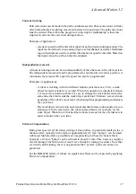
Contour tracking
Path corrections can be made in the path coordinate system. These corrections will take
effect immediately, also during movement between two positions. The path corrections
must be entered from within the program. An interrupt or multitasking is therefore
required to activate the correction during motion.
Example of application:
- A sensor is used to define the robot input for path correction during motion. The
input can be defined via an analog input, a serial channel or similar. Multitask-
ing or interrupts are used to read this information at specific intervals. Based on
the input value, the path can then be adjusted.
Independent movements
A linear or rotating axis can be run independently of the other axes in the robot system.
The independent movement can be programmed as an absolute or relative position. A
continuous movement with a specific speed can also be programmed.
Examples of applications:
- A robot is working with two different stations (external axes). First, a work
object located at station 1 is welded. When this operation is completed, station
1 is moved to a position where it is easy to change the work object and at the
same time the robot welds the work object at station 2. Station 1 is moved inde-
pendently of the robot’s movement, which simplifies programming and reduces
the cycle time.
- The work object is located on an external axis that rotates continuously at a con-
stant speed. In the mean time, the robot sprays plasma, for example, on the
work object. When this is finished the work area is reset for the external axis in
order to shorten the cycle time.
Friction Compensation
During low speed (10-100 mm/s) cutting of fine profiles, in particular small circles, a
friction effect, typically in the form of approximately 0.5 mm “bumps”, can be noted.
Advanced Motion offers a possibility of compensating for these frictional effects.
Typically a 0.5 mm “bump” can be reduced to about 0.1 mm. This, however, requires
careful tuning of the friction level (see User’s Guide for tuning procedure). Note that
even with careful tuning, there is no guarantee that “perfect” paths can always be
generated.
For the IRB 6400 family of robots, no significant effects can be expected by applying
Friction Compensation.
Summary of Contents for IRB 6400R
Page 4: ...Description 20 Product Specification IRB 1400 M97A BaseWare OS 3 0 ...
Page 6: ...Introduction 2 Product Manual ...
Page 10: ...Introduction 6 Product Manual ...
Page 12: ...Product Specification IRB 6400R 2 Product Specification IRB 6400R M99 BaseWare OS 3 2 ...
Page 78: ...Accessories 68 Product Specification IRB 6400R M99 BaseWare OS 3 2 ...
Page 80: ...Product Specification RobotWare 2 Product Specification RobotWare for BaseWare OS 3 2 ...
Page 82: ...Introduction 4 Product Specification RobotWare for BaseWare OS 3 2 ...
Page 104: ...Interbus S 3 2 26 Product Specification RobotWare for BaseWare OS 3 2 ...
Page 110: ...I O Plus 3 2 32 Product Specification RobotWare for BaseWare OS 3 2 ...
Page 128: ...PalletWare 50 Product Specification RobotWare for BaseWare OS 3 2 ...
Page 132: ...Safety 2 Product Manual ...
Page 148: ...System Description CONTENTS Page 2 Product Manual ...
Page 158: ...Structure System Description 12 Product Manual ...
Page 160: ...Computer System System Description 14 Product Manual ...
Page 164: ...I O System System Description 18 Product Manual ...
Page 168: ...Safety System System Description 22 Product Manual ...
Page 170: ...External Axes System Description 24 Product Manual ...
Page 174: ...Installation and Commissioning CONTENTS Page 4 Product Manual IRB 6400R ...
Page 196: ...On Site Installation Installation and Commissioning 26 Product Manual IRB 6400R ...
Page 270: ...Installing the Control Program Installation and Commissioning 100 Product Manual IRB 6400R ...
Page 292: ...Maintenance CONTENTS Page 2 Product Manual IRB 6400R ...
Page 299: ...Maintenance Product Manual IRB 6400R 9 Figure 4 Lubricating gearbox axis 1 4 3 1 2 ...
Page 312: ...Troubleshooting Tools CONTENTS Page 2 Product Manual ...
Page 350: ...Troubleshooting Tools 40 Product Manual ...
Page 352: ...Fault tracing guide 2 Product Manual ...
Page 362: ...Fault tracing guide 12 Product Manual ...
Page 375: ...Motor units Repairs 12 Product Manual IRB 6400R ...
Page 401: ...Arm System Repairs 38 Product Manual IRB 6400R ...
Page 409: ...Cabling Repairs 46 Product Manual IRB 6400R ...
Page 441: ...Special Tools List Repairs 80 Product Manual IRB 6400R ...
Page 479: ...Part List and Spare Parts Product Manual IRB 6400R 38 ...
Page 480: ...Part List and Spare Parts Product Manual IRB 6400R 39 ...
Page 481: ...Part List and Spare Parts Product Manual IRB 6400R 40 ...

